One of the first practical lessons that electronic-circuit designer learn is to be aware of power-rail voltage drop, commonly called “IR drop,” which is the simple product of current and resistance in the printed-circuit board (PCB) track, wire, or larger cable. As currents increase to tens of amps and much higher, the IR-drop problem become more acute. Even a modest 50 mΩ of resistance will result in a 500-mV drop, which is perhaps acceptable at 24 V but almost certainly not for 1-, 3-, or even 5-V rails. The solutions to this problem are easy to describe:
- Use wider PCB traces
- Thicker PCB copper
- Heavier-gauge wire
- Add-on bus bars
But there’s a closely related and absolutely unavoidable consequence of IR drop that is often ignored by circuit designers: the I2R power dissipation and associated temperature rise. This problem is well-known to power companies and electricians. The defining National Electrical Code (NEC) from the National Fire Protection Association spells out how much current a given wire gauge) is allowed to carry under various conditions such as ambient temperature, air flow, and cable bundling in trays and through cable trays and plenums.
Why should a circuit designer care? Two examples—one highly localized, the other broadly diffused—show why this dissipation may be a consideration in designs ranging from a small PC board to installation of Power over Ethernet (PoE) cables.
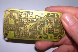
Let’s take the smaller one first with an example based on personal experience. Many years ago, I was involved with the design of a routine circuit board which included wide traces to supply 5 V/2 A with low IR drop, but also handle an occasional 10-A surge, Figure 1. The traces on this double-sided board (no inner layers for power and ground) could easily handle this average and peak current, and we thought we were all set.
Fig 1: A small PC board similar to this one had a short super-thin trace which acted like a fuse when hit with a 10-A surge, despite insignificant IR voltage drop. (Image source: IBFriedrich/TARGET 3001!)
But we weren’t. There was one place on the board layout where real estate was very tight, and the power-rail trace had to make a sharp turn. We figured that this would be no problem: we simply narrowed the trace down to a super-thin hairline width for a few millimeters at the turn, then expanded it back to the original size. The increase in DC resistance where we did that was insignificant with respect to IR loss.
Except it actually was significant, but in way we didn’t anticipate. We started getting field failures due to an “open” power-rail, and soon figured it out. The 10-A current surge through that sliver of trace was causing highly localized heating, and the thermal of the trace couldn’t dissipate it fast enough. There’s a name for that physical structure: fuse. The sharp and rapid increase in I2R dissipation at the hairline trace was putting it on the edge of self-induced burn out. It didn’t happen every time the current surged, but it did at some point in the field. We had to recall all the boards, and luckily were able to rework them by soldering on a discrete wire to supplement the PC trace.
In contrast, the slow, steady cable-heating issue is more subtle and often has no easy solution. The first standard for PoE (IEEE 802.3af-2003) limited the delivered power to about 15 W , while the subsequent upgrade (IEEE 802.3bu-2016, often referred to as PoE+) doubles that to about 30 W. Either rating is low enough that the resultant dissipation in the Ethernet cable was only a few watts.
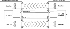
However, the recently ratified third version of the PoE standard (IEEE 802.3bt, often called PoE++) supports power to about 100 W, and each conductor in the cable can carry up to 1 A under some circumstances, Figure 2. Since the wire gauge is thin with end-to-end resistance up to 12.5 Ω, the math easily shows that the cable dissipation can reach 12.5 W. That modest amount of heat is not a problem for a cable in free air as the dissipation is spread along its entire length and is not concentrated.
Fig 2: The recently approved third version of the Power-over-Ethernet allows for substantial power in the thin wires, which can result in excessive self-heating and performance degradation, especially in constrained installations. (Image source: Advantech B+B SmartWorx)
However, many PoE cables are not in free air. Instead, they are tightly packed with higher-power AC cabling, and run in ducts and plenums with little or no convection airflow, while the building’s ambient temperature in these hidden areas can be easily be in the 100oF (38oC) range. Add to this heat from the nearby AC cables and the PoE cables can get fairly hot. They will not get hot enough to start a fire since the insulation of qualified cables is highly resistant to ignition nor will it sustain a fire. However, temperature rise does affect performance of data cables, especially in terms of insertion loss and associated bit error ratio (BER). [Side note: unfortunately, there are many substandard counterfeit cables out there, but with legitimate-looking approvals on the box and insulation—that doesn’t end well.]
Unfortunately, the solution to after-the-fact realization of excessive temperature rise is painful and usually involves pulling and re-routing the PoE cables. There are standards from the NEC and the Telecommunications Industry Association (TIA) that address the issues of what is acceptable; however, the NEC focuses on safety, while the TIA focuses on performance. In general, the standards recommend mitigation through a combination of reducing the aggregate bundle size (number of discrete wires), spreading the cable out via an open cable tray to provide air circulation; and using a cable with a larger conductor size. All of these are far easier to implement during design and installation phase than to fix afterwards.
The lesson is clear, even though IR-induced voltage drop may no be a problem: I2R thermal dissipation may be, and it be a problem at both extremes of physical realization from a tiny, nearly invisible, tiny PC board track to longer, highly visible wire cables. Do the simple math and associated modeling on dissipation and temperature rise to make sure you are in the “OK” zone.
References
Cabling Installation and Maintenance, “Can your UTP cables take the heat of PoE?
Cabling Installation and Maintenance, “The heat is on: Meeting high-power PoE at longer distances”


