By: Lisa Mitterhuber, Julien Magnien, Elke Kraker
Introduction
Twenty years ago, a lamp had exactly one purpose—to illuminate the room. A typical incandescent lamp lasted a year and failure was caused by a filament or/and a glass breakage [1]. Nowadays typical lighting is based on LED technology, which is considered as durable. Due to the fact that many materials are interacting in such a lighting system, the variety of failure modes is increasing too. Therefore, design and material issues are critical to the reliability of such an electronic system. Its testing is crucial to guaranteeing a long-lasting LED system.
Particular attention must be paid to thermal management [2], as thermal stress is one of the main triggers of failure modes in electronic systems. To predict the lifetime of the LED system and to ensure its reliability, knowledge about critical failures is needed. In this paper, an LED module based on four flip-chip LEDs is investigated in terms of design for reliability and aging phenomena during a supply switching test (SST), by using thermal impedance analysis.
Test Device and Methodology
The investigated LED module consists of four blue flip-chip LEDs, electrically connected in series by SnAgCu (SAC305) solder joints on the copper electrodes of a printed circuit board (PCB). Here, the LED module has no underfill. The PCB was mounted on a liquid-cooled heat-sink via thermal interface material (TIM). A schematic of the flip-chip (fc) LED-module can be seen in Figure 1a.
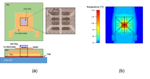
The supply switching test (SST) was applied for reliability testing. This SST leads to active heating due to the power losses occurring at the LED junction. The LED module was mounted on a heat-sink (Ts=8°C). Then a power load of 7 W was used for heating up the system to Tj=125°C with a dwell time of 30s. Afterward, the system was switched off, also with a dwell time of 30s. This cycle was repeated to investigate the aging phenomena of the LED module and to gain knowledge of the anticipated service life of the package [3]. The active current based heating of the LED module was done using a commercial programmable power supply [4]. At the beginning and during the SST, the LED modules were monitored thermally to control their thermal performance and to analyze their reliability. The evaluation of the thermal performance of the LED module was carried out by thermal impedance analysis. The experimental investigations were done by using a commercial thermal test apparatus and accompanying analysis software [5] according to the JESD 51-14 standard [6][7].
A simulation was carried out for the thermal heat path using commercial finite volume software [8]. Both in the experiment and in the simulation, structure functions were generated. The structure function represents the heat path in the LED module from the junction to the heat sink as a thermal equivalent network of thermal resistances and thermal capacitances in a one-dimensional way. The comparison of these structure functions enables verification of the thermal model. The validated structure function provides an understanding of the heat path within an LED module [9]. By adjusting one specific parameter in the simulation, changes in the structure function can be used to identify the source of variations in the heat path of the LED system [10][11]. E.g., a “virtual” dual interface experiment can be performed by varying the thermal conductivity of the TIM.
The Initial State of the LED and Its Aging Phenomena
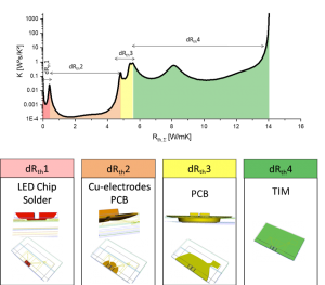
Before starting the reliability testing, the initial state of the LED system was determined by the thermal impedance analysis. The structure functions were generated from both measurement and finite volume simulation. The structure function was divided into four different sections (dRth1-4). The dRth sections were chosen to be the distance between two significant peaks in the structure function (see Figure 2) [12]. Each section can be interpreted as a different region along the heat path of the LED system. The corresponding validated thermal simulation enabled each of these sections to be associated with real physical regions in the LED system. Figure 2 shows the four dRth sections of the structure function and their corresponding region in the LED system, represented as isotherms. The temperatures of the isotherms are the maximum temperature of each dRth section. The dRth4, which was assigned to the attachment of the LED module to the heat sink, the TIM, had the largest thermal resistance in the system followed by the PCB (dRth2).
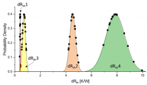
To analyze if an LED system undergoes a significant change in its thermal performance during the SST, all the LED systems were subject to an initial control. Here, 15 LED systems underwent the SST and their initial thermal resistance of each LED system was analyzed. The initial status of dRth1-4 of all 15 LED system is shown as probability density functions in Figure 3. This analysis showed a Gaussian-shaped distribution of dRth1-4. dRth4, the attachment of the LED module to the heat-sink had the broadest range, followed by the dRth2, dRth3, and dRth1.
The thermal impedance analysis allows us to check the LED system’s performance in each SST cycle. During the SST the thermal total thermal resistance became higher with the number of cycles. This indicates that there were structural changes within the LED system. To reveal the root cause of the structural changes, the dRth sections were analyzed during the SST and material parameters of validated simulation were varied systematically. Degradation of the materials in the LED system can be assigned to changes in the heat path. This procedure is described in more detail in [11]. There, it was shown that even though the dRth4 had the largest distribution initially, it stayed nearly constant during the SST. This indicated no degradation of the mounting over the whole SST runtime. dRth1 and dRth2 increased significantly with the number of cycles, pointing out that the connection between LED chips and the PCB is mainly affected by the SST. Concluding the dRth analysis of the SST, the aging of this interconnection was found to contribute to the increase of the thermal resistance and hence the junction temperature in the fc LED module. [11]
Predicting the Lifetime of the LED Module
The information that the aging of interconnection is one of the major reliability concerns in the LED system can be used to create a reliability model. A reliability model allows for forecasting the number of cycles until failure and hence the remaining lifetime by using a parameter-driven monitoring model. The reliability model was generated empirically by using the change of the thermal resistance over the number of cycles. The parameter-driven monitoring model can be expressed as,
(1)
where Rth is thermal resistance at a specific number of SST cycles, Rth,0 is the initial thermal resistance of the device, PH is the heating power, coefficient ΔTpc is the initial set temperature swing of the SST, N is the number of SST cycles, and C and B is the empirically determined power law. A more detailed description can be found in [13].
Equation 1 shows that two parameters are significant for the reliability model: the initial thermal resistance of the LED-module and the used power load in the SST. The higher the applied power and the thermal resistance of the LED-system, the higher the temperature swing during testing.
The magnitude of the temperature swing determines how fast the material degrades. The reliability model also revealed that there is a minor interaction between the two parameters, the initial total thermal resistance, and the power load. [14]
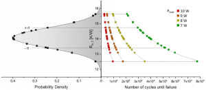
The left-hand axis of Figure 4 shows the statistical distribution of the total thermal resistance of the LED system with its associated sigma level. The number of cycles until failure increases up to 37 times comparing the LED system with the highest (15.6 K/W) and the lowest (12.5 K/W) thermal resistance. As previously mentioned, this initial thermal resistance is mainly influenced by the attachment of the LED module to the heat-sink (see Figure 3).
The reliability model for different power loads is shown in Figure 4 on the right-hand axis. The thermal resistance values with the power load of 7 W are determined experimentally; the other values with a higher power load were calculated from the model. For an LED system with an average thermal resistance of 14 K/W, it was shown that a reduction of power from 10 W to 7 W (a relative increase of 43%) causes an eight times higher number of cycles until failure. This is caused by the lower temperature swing, which results in lower mechanical stress in the interconnections and accordingly implies slower fatigue. [13]
Conclusion
The thermal impedance analysis was used to investigate the major reliability concern of an fc LED module. In-depth analysis of the impedance measurement, in terms of the corresponding structure functions and their dRth section, combined with thermal simulations confirmed solder fatigue as the main aging phenomena. Based on this, a reliability model for an SST was developed to describe the aging of an fc LED module. The lifetime of the package strongly depends on the temperature swing experienced during the SST, which is determined by the initial thermal resistance and the applied power load during testing.
Acknowledgment
The authors gratefully acknowledge the financial support under the scope of the COMET program within the K2 Center “Integrated Computational Material, Process and Product Engineering (IC-MPPE)” (Project No 859480). This program is supported by the Austrian Federal Ministries for Transport, Innovation, and Technology (BMVIT) and for Digital and Economic Affairs (BMDW), represented by the Austrian research funding association (FFG), and the federal states of Styria, Upper Austria, and Tyrol.
References
[1] O. Horacsek, “Properties and Failure Modes of Incandescent Tungsten Filaments.,” IEE Proc. A Phys. Sci. Meas. Instrumentation. Manag. Educ. Rev., vol. 127, no. 3, pp. 134–141, 1980.
[2] M.-H. Chang, D. Das, P. V. Varde, and M. Pecht, “Light emitting diodes reliability review,” Microelectron. Reliab., vol. 52, no. 5, pp. 762–782, May 2012.
[3] J. Hegedüs, G. Hantos, and A. Poppe, “Reliability Issues of Mid – Power LEDs,” in THERMINIC 2019 – 25th int. workshop on Thermal Investigations of ICs and Systems, 2019.
[4] Keithley, “Single-Channel Programmable DC Power Supplies ‘Model 2200-30-5, Keithley Instruments®.’” [Online]. Available: https://www.tek.com/tektronix-and-keithley-dc-power-supplies/keithley-2200-dc-power-supply. [Accessed: 24-Jan-2020].
[5] Mentor Graphics Corporation (Ed.), “T3Ster® V1.5, Mentor Graphics®.” [Online]. Available: http://s3.mentor.com/public_documents/datasheet/products/mechanical/products/t3ster-technical-info.pdf. [Accessed: 24-Jan-2020].
[6] JEDEC Standard, “JESD51-14 – Transient Dual Interface Test Method for the Measurement of the Thermal Resistance Junction to Case of Semiconductor Devices with Heat Flow Trough a Single Path,” 2010.
[7] A. Poppe, “Testing of Power LEDs: The Latest Thermal Testing Standards from JEDEC,” Electronics Cooling, 2013. [Online]. Available: http://www.electronics-cooling.com/2013/09/testing-of-power-leds-the-latest-thermal-testing-standards-from-jedec/. [Accessed: 07-Apr-2015].
[8] “FloTherm® V12.1, Mentor Graphics®.” [Online]. Available: http://s3.mentor.com/public_documents/datasheet/products/mechanical/products/flotherm.pdf. [Accessed: 24-Jan-2020].
[9] L. Mitterhuber et al., “Validation methodology to analyze the temperature-dependent heat path of a 4-chip LED module using a finite volume simulation,” Microelectron. Reliab., vol. 79, pp. 462–472, 2017.
[10] A. Alexeev, G. Martin, and G. Onushkin, “Multiple heat path dynamic thermal compact modeling for silicone encapsulated LEDs,” Microelectron. Reliab., vol. 87, pp. 89–96, 2018.
[11] L. Mitterhuber et al., “Thermal Transient Measurement and Modelling of a Power Cycled Flip-Chip LED Module,” Microelectron. Reliab., vol. 81, pp. 373–380, 2018.
[12] A. Poppe, “Dynamic Temperature Measurements: Tools Providing a Look into Package and Mount Structures,” Electronics Cooling. [Online]. Available: https://www.electronics-cooling.com/2002/05/dynamic-temperature-measurements-tools-providing-a-look-into-package-and-mount-structures/. [Accessed: 24-Jan-2020].
[13] J. Magnien et al., “Parameter driven monitoring for a flip-chip LED module under power cycling condition,” Microelectron. Reliab., vol. 82, pp. 84–89, 2018.
[14] J. Magnien et al., “Reliability and Failure Analysis of Solder Joints in Flip Chip LEDs via Thermal Impedance Characterisation,” Microelectron. Reliab., vol. 76–77, pp. 1–5, 2017.
About the Authors
Lisa Mitterhuber | Lisa.Mitterhuber@mcl.at
Lisa Mitterhuber is working as a senior scientist in the department of materials for microelectronics at the Materials Center Leoben in Austria. She studied Technical Physics at the University of Technology in Graz from 2010 to 2016. In 2019 she got her Ph.D. degree in materials science at the Montanuniverstät Leoben. During her thesis she was developing a scale-bridging methodology of the thermal transport in microelectronic devices, considering both wafers as well as package level.
Julien Magnien | Julien.Magnien@mcl.at
Julien Magnien graduated from the Karl Franzens University of Graz in 2010 with a master’s degree in physics and received the Ph.D. degree from the University of Vienna in 2015, focused on the reliability of solder interconnection technologies. Since 2015, he is working at the Materials Center Leoben in the field of reliability and lifetime modeling for microelectronic packages. The main activities compromise the development of reliability monitoring models based on temperature-sensitive electrical parameters, and parameter-driven lifetime prediction.
Elke Kraker | Elke.Kraker@mcl.at
Elke Kraker studied physics at the University of Graz where she obtained her master’s degree in 2004. Afterward, she started her Ph.D. studies at the University of Graz focusing on opto-chemical sensors combined with organic electronics and received her PhD in 2008. In 2012 she joined the business unit “Materials for Microelectronics” of the Materials Center Leoben Forschung GmbH and works there as leader of the “Reliability and Analytics for 3D Integration & Packaging” group. The main focus lies on the development of tests and methods for material characterization in the field microelectronics, development and evaluation of reliability tests.
