Introduction
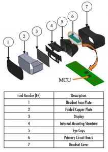
Wearable technology is a growing market, projected to reach $2.78 billion in revenue by 2024 [1], and comfort is a major factor driving sales for these devices. Ergonomics and ease of use were cited as major factors in the decision to purchase a virtual reality (VR) headset in a recent consumer survey [2]. While weight and form factor are certainly ergonomic factors to be considered, this study focuses on perspiration mitigation during prolonged use of a commercially available VR headset. The junction-to-ambient resistance, Rja, of a commercially available headset was found to be 29.1 K/W at steady-state. However, a first-law analysis showed that 28.6% of the heat generated was being directed to the user’s forehead. Thermocouples placed around the periphery of the headset showed an immediate temperature spike of 2.8°C when the headset was removed from the user after 2 hours of use. A maximum local temperature increase of 5.6°C was seen at the top of the headset directly above the device’s microcontroller unit (MCU) [3]. From this data, the team hypothesized that more effective spreading of the heat away from the MCU would increase the available convective surface area, redirect heat away from the user’s forehead to periphery areas around the headset, and improve user comfort during prolonged operation. The integration of a copper sheet bent to match the contour of the headset, shown as FN 2 in Figure 1, was shown to increase the effective surface area for convection by 61% and decrease the temperature directly above the MCU by 6.5°C [3].
Experimental Facility, Procedures, and Analytical Approach
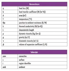
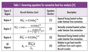
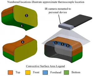
Six thermocouples were placed around the periphery of the headset as shown on Figure 2. These thermocouples were used to measure the surface temperature of the headset for subsequent convective heat loss analysis. It was assumed that each thermocouple temperature was reflective of the entire surface region upon which it was placed. For example, the measurement at thermocouple 5 on Figure 2 was assumed to be the temperature of the entire faceplate, highlighted as yellow. The governing Nusselt number equations (Equations 1-3) corresponding to each region are shown in Table 1. Utilizing Equation 4, the corresponding heat transfer coefficient was used in Newton’s Law of Cooling, Equation 5, to determine the convective heat loss from each region. The characteristic length, Lc, of each surface was found by dividing the surface area of each area of interest by its perimeter. The ambient temperature was measured with a thermocouple calibrated to a NIST-traceable thermistor accurate to within ±0.2°C. All of the thermocouples used around the periphery of the headset were calibrated to the same thermistor.
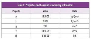
In order to determine the heat loss from the headset, a first-law analysis was conducted, the individual losses calculated from Equation 5 for each region were summed together. All relevant thermophysical properties used during calculations are shown in Table 2. The transient input power data was acquired from a USB-compatible measurement device [5]. The resulting power draw waveform can be described by a sinusoidal curve with a central tendency, or average power draw, of 3.52 W at a sampling frequency of 5 kHz with a standard deviation of 97 mW. The heat loss directed to the user is the difference between the convective heat transfer losses over Region 4, 5, and 6 (Figure 2), and the input power data. The OTS configuration had the heat leaving the MCU by natural convection only. When the spreader was added to the MCU a thin layer of thermal interface material epoxy (k = 0.8 ~ 1.4 W/mK) was used to bond the spreader to the 400 micron thick copper spreader. From the spreader it was then allowed to naturally convect to the shell of the headset.
The test procedure was developed to simulate prolonged use at steady-state conditions. Eight participants were asked to play a game on the VR headset for 100 minutes. The system was removed and then powered off for a 20-minute cool down period. This test was conducted for two headset configurations: off-the-shelf (OTS) versus spreader integrated configuration. Tests were conducted in the same laboratory environment where the ambient temperature fluctuated by ±0.3 °C. All users played the same game in an effort to control activity across participants to moderate levels. Users were then given a survey to ascertain the degree of perspiration, if any, was affected by the integration of the heat spreading thermal management approach. With this spreader in place, users reported a 25% reduction in perspiration during prolonged use [3].
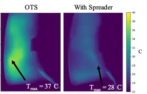
Testing showed that the assumption of temperature uniformity on the top face, shown as Region 4 in Figure 2, needed to be corrected [3]. IR imaging was implemented using a cellular phone compatible camera oriented normal to the top face as shown in Figure 2 [6]. Figure 3a is an IR image of the headset with no internal heat spreading, while Figure 3b implements the copper spreader (FN 2, Figure 1). Figure 3a shows each headset at steady state with the VR on its home screen without attachment to a user. A central hot spot, which is approximately where the top thermocouple was placed (shown as thermocouple 4 on Figure 2), is visible on the OTS configuration IR image (Figure 3a). Implementation of the internal heat spreader shows a drastic reduction in surface temperature across the entire surface, as illustrated in Figure 3b. With the increased spatial resolution of the IR measurement approach, down to 70 microns for the field of view (FOV) used, these temperatures were used in an improved convective heat transfer analysis of losses through the top surface. The losses through the front and bottom faces were found to be relatively small [3]. Therefore, the improved IR temperature measurement method was only applied to the top surface where the largest in-plane temperature gradients were observed. The first law analysis used the average of all the temperatures measured in the FOV of the IR Imager as the top surface temperature. The thermocouple measurements at locations 5 and 6, illustrated on Figure 2, were used as the surface temperature for the faceplate and bottom surface, respectively. The transient power measurement device was still used for the total input power to the control volume.
Results and Discussion
Transient temperature data and convective heat losses for the top surface are shown in Figure 4 and Figure 5, respectively.
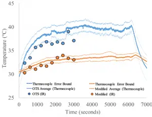
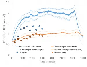
The solid lines of Figure 4 and Figure 5 are measurements and calculations made with the thermocouple placed on the top surface as shown in Figure 2. The dashed lines above and below the solid lines represent the range of values from measurement error, accounting for inherent instrument error and random error from the transient data of all eight participants. The solid dots of Figure 4 and Figure 5 are the results of measurements and calculations made with the IR camera positioned above the top face as shown in Figure 2. The color indicates the OTS versus integrated spreader headset, blue and orange respectively. Once steady state is reached, there is an approximate 6.5°C difference in the average top surface temperature recorded with the thermocouples between the OTS and modified configurations. Using IR measurements, this difference drops to approximately 3.3°C as the colder regions of the OTS headset are more accurately accounted for with this measurement technique.
In both instances, however, the top surface temperature drops dramatically with the integration of the internal heat spreader, a conclusion corroborated qualitatively with the difference in steady-state IR images provided in Figure 3. With the heat spreader integrated, the IR measurements fall within the error band for the thermocouple-based temperature measurements, while they do not for the OTS configuration. The accuracy of the thermocouple-based measurement for the integrated heat spreader solution is an artifact of the temperature being distributed more uniformly, which presents more isothermal conditions than the OTS configuration. The need for more spatially resolved IR measurements for the assessment of wearable technology is more evident in the convective heat loss data shown in Figure 5.
The measurement with the IR camera falls well outside the error band for the OTS configuration when assessed with locally placed thermocouples. To further corroborate the two measurement techniques, the temperatures measured with IR at the location of the top surface thermocouple were compared. The temperatures recorded at the thermocouple location were within 0.05°C and 0.70°C when compared with the IR imaging for the modified and OTS configurations, respectively. Natural logarithmic analysis of the transient data leading up to steady-state was used to determine the effective thermal time constant for both configurations. Introduction of the internal heat spreader increases the time constant by one order of magnitude from the OTS configuration value of 320 seconds.
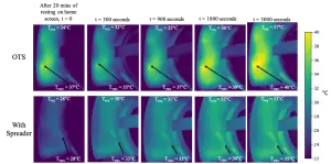
The transient IR images shown in Figure 6 for both the OTS and modified configurations illustrate how the heat spreads differently between the two designs. For the OTS configuration, there is a bottleneck to heat transfer located centrally around the MCU. However, the heat spreader serves to distribute the heat more uniformly, relieving much of the temperature rise above the MCU. This bottleneck creates an average four degree increase in the overall ΔT across the surface. Heat clearly reaches the top surface more effectively with the internal heat spreader integrated.
Without a more accurate representation of the temperature distribution around these side and bottom faces, it is currently impossible to accurately quantify the amount of heat loss being directed at the user’s forehead. There are innovative solutions to measuring the amount of perspiration, motivated primarily by the exercise science/kinesiology community, which may be used to validate the analytical assessment of the heat transfer deficit being inflicted on the user during prolonged play [7].
Conclusion
IR imaging showed that heat generated from the headset MCU can be more effectively spread throughout the headset with relatively simple modifications, resulting in an overall more comfortable user experience. Though in moderate use, approximated as 20 minutes or less by the data collected, a user may not feel an uncomfortable amount of perspiration/fatigue. However, for prolonged use in VR training for plant operators, military personnel, and athletic training, the addition of such a spreader would result in more comfortable training sessions for the user, enabling this technology to make inroads in low-risk virtual training/activity environments.
About the Authors
Rachel McAfee
Rachel McAfee is an undergraduate Mechanical Engineering student at Oregon State University. She has completed internships with Intel’s development lab for High-Performance Computing and U.S. Army Research Laboratory. Her research is focused on electronics thermal management including two-dye laser-induced fluorescence measurements of fluidic systems. Rachel is the Chair of OSU Overclocking and Event Coordinator for Out in STEM.
Matt Harrison
Matt Harrison is a Ph.D. student in Mechanical Engineering at Oregon State University. He received a Bachelor of Science from Oklahoma State University in Mechanical Engineering in 2015. His work experience includes two years as a project engineer at Koch Industries, a research fellowship at Instituto Superior Technico in Lisbon Portugal, and an internship at Google. His research interests include electronics thermal management utilizing multiphase heat transfer, supercritical CO2 cooling applications, synthetic jet characterization, and liquid nitrogen applications for competitive overclocking. Matt is slated to graduate in the summer of 2020.
Joshua Gess
Joshua Gess received his Ph.D. from Auburn University in Mechanical Engineering in 2015 and his B.S. in Mechanical Engineering from Vanderbilt University in 2005. Prior to receiving his Ph.D., he spent six years in the defense industry at Northrop Grumman in Madison, AL designing mobile command centers for Army, Navy, Marines, and National Guard customers. His research is focused on energy-dense electronics thermal management and fundamental multiphase heat transfer. He has developed a two-phase Particle Image Velocimetry (PIV) technique to calculate net coolant flow rates to boiling surfaces and built the first supercritical CO2 cold plate for processor-scale cooling.
References
- IMARC Group, 2019, “Industrial Wearable Devices Market: Global Industry Trends, Share, Size, Growth, Opportunity and Forecast.” Available: https://www.imarcgroup.com/ industrial-wearable-devices-market
- International Data Corporation, 2018, “VR Headset Market Rebounds as Standalone Products Gain Traction while AR Headset Market also saw Positive Movement,” Available: https://www.idc.com/getdoc.jsp?containerId=prUS44509518
- R. McAfee, C. Haxton, M. Harrison, and J. Gess, 2020, “Thermal Characterization of a Virtual Reality Headset during Transient and Resting Operation” in Proc. of Semiconductor Thermal Measurement and Management Symposium (SEMITHERM), San Jose, CA.
- Bergman, T. L., Lavine, A. S., Incropera, F. P., & DeWitt, D. P. (2011). Fundamentals of heat and mass transfer. Hoboken, NJ: Wiley.
- Monsoon Solutions High Voltage Power Monitor (Part Number: AAA10F)
- Flir One Pro, https://www.flir.com/products/flir-one-pro/
- Gao, W., Emaminejad, S., Nyein, H. et al. Fully integrated wearable sensor arrays for multiplexed in situ perspiration analysis. Nature 529, 509–514 (2016). https://doi.org/10.1038/nature16521

