The selection of heat-spreader materials is an important consideration for cooling modules in handheld electronic systems. Heat spreaders are typically used in close contact with the source of heat. This can be, for example, a subcomponent, chip, or microelectronic package. The heat spreader transfers and distributes heat from the source to a heat sink through a thermal interface material, or in some cases directly to air.
The Need for Heat Spreaders
The primary reason for using heat spreaders is to move the heat away from the source and avoid over-heating the electronic components. Localized high temperature centered around the source of heat, known as a hot spot, can be detrimental to the reliability and efficiency of the device. Another reason for using a heat spreader is to distribute the heat evenly over the surface of the device and reduce the peak surface temperature. This is important for the comfort of the user handling the device.
While heat spreaders have many advantages, they also present challenges. Device designs require higher power density, miniaturization of devices, and the ever increasing need to reduce weight and cost. However, traditional thermal solutions like heat spreaders do the exact opposite—they add volume, cost, and weight. This challenge makes it critical to seek out alternate thermal management materials that can adapt to the current needs of the industry.
Attributes of a Good Heat Spreader
A successful heat spreader needs to rapidly move heat away from the source—the hot spot—and spread it over a wider area, but what characteristics make this possible? First, the X-Y (or in-plane) thermal conductivity of the heat-spreader material should be high. The heat spreader also needs to prevent the heat from reaching the surface of the device, thus minimizing the hot spots that the user handling the device experiences. Hence, the Z-direction (or out-of-plane) thermal conductivity of the heat-spreader material should be low. Finally, the heat spreader should not take up too much space since internal device volume is limited—thinner heat spreaders are always preferred.
Traditional Heat Spreaders
It is common practice to use stainless steel with pyrolytic graphite films to manage heat in handheld devices. Disassembly of a device, such as a smartphone, will reveal these graphite films adhered to structural components such as shields, mid-plates, or chassis. When using these materials, one must account for the thickness of the adhesive layer that is required to attach these films to the metal substrates. This adhesive can often be 25 μm thick, adding to the volume of the heat spreader without providing any thermal or structural benefit. It also involves an additional manufacturing step that can increase the cost and complexity of device assembly.
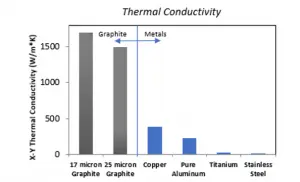
Figure 1 shows the X-Y thermal conductivity of a few common materials. The left-hand side shows that the pyrolytic graphite materials have high thermal conductivity of 1,500 to 1,700 W/m-K. On the right-hand side are metals such as copper with thermal conductivity close to 400 W/m-K, aluminum with thermal conductivity close to 220 W/m-K, and titanium and stainless steel with very low thermal conductivities, less than 20 W/m-K.

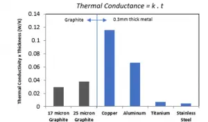
However, consideration for thermal conductance (also known as bulk conductivity), which is a measure of the amount of heat that can be moved through the material, changes the analysis. Figure 2 shows thermal conductance, defined as thermal conductivity, multiplied by thickness for the same materials. The pyrolytic graphite films, because of their low thickness (17 to 25 μm), have low thermal conductance. As stated above, these graphite films also need to be adhered to a structural metal substrate like stainless steel, which could be 0.25 to 0.3 mm thick.

In contrast, 0.3 mm thick copper has thermal conductance three to four times higher than that of the graphite. Similarly, 0.3 mm thick aluminum has thermal conductance one and a half to two times higher than the graphite. Thus, thermal conductance, which is the amount of heat that the heat spreader can move away from the hot spot, is a more important consideration than the thermal conductivity of the heat-spreader material.
Traditionally, the thermal and structural requirements of electronic devices have been considered separately. A perfect example of this is the graphite film for thermal purposes and stainless steel for structural purposes discussed above. An alternative approach is to solve both the structural and thermal challenges using one material that has both the thermal and structural properties desired.
If the structural member within the device was also the heat spreader, then the need for secondary solutions, such as the pyrolytic graphite films, would be eliminated. By harnessing the concept of thermal conductance, conventional metals such as stainless steel, copper, and aluminum could be used to move heat more efficiently.
Selecting the Right Thermal and Structural Materials
Aluminum has good thermal conductivity (220 W/m-K) and is a relatively low-cost material. Copper has a slightly higher cost as compared to aluminum but has significantly higher thermal conductivity (400 W/m-K). Magnesium has moderately high thermal conductivity (160 W/m-K) but is also more expensive. Pyrolytic graphite has high thermal conductivity (1,500 to 1,700 W/m-K) but also comes at a significantly higher cost as compared to common metals.
Stainless steel is a commonly used structural metal. It has low cost and a high elastic modulus (193 GPa). Aluminum and magnesium have a low elastic moduli (69 GPa and 45 GPa, respectively). Molybdenum has a high elastic modulus (330 GPa), but its high cost makes it impractical for use as a structural metal in handheld electronics.
Conducting elastic modulus/cost and thermal conductivity/cost analyses shows that an ideal heat-spreader material would have the elastic modulus of stainless steel and the thermal conductivity of aluminum or copper.
Structural Properties
It is unlikely that an electronic device will be subjected to a tensile load. It is more likely that it will be loaded in bending or torsion due to accidental mishandling. Examples of this could be a tablet computer in a heavy backpack or a seated user with a cell phone in their pocket. In loading under bending, the stiffness and strength of structural materials are provided by their outer skins. Hence, structural materials used in electronic devices act like I-beams used in construction. Like an I-beam, the core of a structural material in electronic devices does not contribute significantly to its stiffness or strength. The core is mechanically underutilized and provides limited structural benefit.
Precision Cladding Offers a Solution
The standard design approach for structural materials in electronic devices is to use solid stainless steel. However, since the core is structurally underused, it could be removed, and replaced with a high-conductivity material, thus achieving the best performance from both materials. This would provide a heat spreader with high strength and stiffness in the skins and high conductivity in the core.
This composite structure with high-stiffness skins and high-conductivity cores can be achieved through a process known as precision cladding. Precision cladding is a high-volume, reel-to-reel process that has been used for industrial applications for many decades. The first step in precision cladding is to roll the skin and core materials together under extremely high pressures. This is known as roll bonding, and it involves large plastic deformations (up to 75%) that create new surface area (up to 4X) at the interfaces between the metals. The native oxide layers on the metal surfaces are broken apart and dispersed, which leads to metal-to-metal bonding.
Roll bonding is followed by a heat-treatment step during which the elements in the clad metals diffuse across the interfaces and stabilize them. This diffusion-based metallurgical bonding of the metal layers is extremely strong and does not come apart in subsequent manufacturing processes such as stamping or forming of the heat spreader. It is important to note that there is no secondary bonding layer or adhesive that is used to create the precision-clad material. It is instead created by high rolling pressures and heat treatments that create strong metallurgical bonds between the three metal layers.
Figure 3 shows a cross-sectional view of a precision-clad stainless steel-copper-stainless steel heat-spreader material. The stainless-steel skins provide the desired strength and stiffness while the copper core provides the desired thermal conductance. Such clad materials can also be made with aluminum cores.

Optimum Clad Skin-to-Core Thickness Ratio
To determine the optimum skin-to-core thickness ratio for these composite heat spreaders, consider the example of a precision-clad stainless steel-aluminum-stainless steel material. The flexural modulus of the heat spreader increases with growing thickness of the stainless-steel skins since stainless steel has a higher elastic modulus compared to aluminum. Increasing the stainless steel thickness decreases the thermal conductivity of the heat spreader since stainless steel has a significantly lower thermal conductivity than aluminum. The normalized product of modulus and thermal conductivity exhibits a maximum at approximately 15% stainless steel thickness per side. Such a clad heat spreader, with 15% stainless steel skin thickness on each side and 70% aluminum core thickness, would have 80% the flexural modulus of solid stainless steel (154 GPa), 10 times the X-Y thermal conductivity of solid stainless steel (160 W/m-K), and only 53% the density of solid stainless steel (4.2 g/cm3).
Comparing the Thermal and Structural Performance of Heat Spreaders
Figure 4 shows two heat-spreader configurations. On the left is a 200 μm thick precision-clad stainless steel-copper-stainless steel heat spreader with a thickness ratio of 20% stainless steel skins on either side and a 60% copper core. On the right is 200 μm thick stainless steel with a 25 μm thick graphite film. As noted previously, the graphite film requires an adhesive, which adds 25 μm to the thickness of the heat spreader, for a total thickness of 250 μm.

Although the stainless steel-copper-stainless heat spreader has 50 μm lower thickness, its thermal conductance (0.049 W/K) is nearly 20% higher than that of the stainless steel plus graphite heat spreader (0.041 W/K). This is due to the high thermal conductivity of the copper core in the clad heat spreader.
Comparing the structural performance of these heat spreaders, the 200 μm thick clad stainless steel-copper-stainless steel heat spreader has an 80% higher effective bending modulus (179 GPa) as compared with the 250 μm thick stainless steel with graphite heat spreader (99 GPa). This is because the bending modulus is proportional to the thickness cubed (t3). As a result, the structural performance of the solid stainless-steel heat spreader degrades as the graphite film occupies a larger fraction of the thickness.
Improving both the thermal and structural performance allows the thermal engineer to design a thinner heat spreader, leaving additional room for other functional components within the handheld electronic device.
Experimental Comparison of the Thermal Performance of Heat Spreaders
Laboratory experiments were conducted to compare the thermal performance of various heat-spreader configurations. The test samples had dimensions of 104 mm x 57 mm x 0.55 mm. A copper slug, continuously heated by a hot plate, was used to simulate a localized hot spot on the sample. A thermal imaging camera was used to track the spread of heat over the sample surface as a function of time.
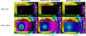
Three sample configurations were tested—bare stainless steel, stainless steel with a graphite film, and precision-clad stainless steel-aluminum-stainless steel. Figure 5 shows thermal images of the sample surfaces as a function of time. The top row shows the thermal images at time T = 0 seconds, immediately after each sample was individually placed on the hot plate. The bottom row shows the thermal images at time T = 120 seconds.

After 120 seconds, the bare stainless steel sample showed the highest hot-spot temperature (54.9°C), followed by the stainless steel with graphite film (44.4°C) sample, and the precision clad stainless steel-aluminum-stainless steel sample (42.6°C). In addition, there were significant differences in the surface-temperature differentials (ΔT) between the three heat-spreader configurations. The bare stainless-steel sample showed a ΔT of 24°C. The stainless steel with graphite film sample showed 50% improvement, with a ΔT of 12°C. The precision-clad stainless steel-aluminum-stainless steel sample showed a significantly higher 75% improvement as compared to the bare stainless steel, with a ΔT of only 6°C. This thermal-performance improvement can be attributed to the significantly higher thermal conductance of the aluminum core in the clad composite heat-spreader sample.
Summary
Precision-clad heat spreaders with stainless-steel skins and copper or aluminum cores can be designed to occupy less volume and improve the thermal performance and power consumption of handheld electronic devices. Reducing the thickness of the heat spreader using precision-clad composite materials can provide more room for larger batteries or other functional components. Applications for these materials can include cases, frames, chassis, electromagnetic shields, or other structural components that do not provide a thermal benefit in their current form.


