The role of a heatsink is to provide a conduction path from a heat source that is to be cooled to a volume of cooling fluid. The heatsink’s surface area that fills that volume is considerably larger than the surface area of the heat source. In this way, the heatsink acts as an ‘area extender’.

For a given heat flow (Q) and convective heat transfer coefficient (h), any increase in the surface area will result in a decrease in the temperature rise of the source over ambient (Equation 1). Filling a design volume with a shape with a large surface area has its drawbacks, however. If the surface area is too large the fluid flow channels through it will be very narrow. This can result in thermal choking where the fluid temperature attains a similar temperature to the heatsink surface and thus little heat transfer is achieved. In addition, any fluid approaching the heatsink will be more likely to divert around it or, for a ducted heatsink, a bigger fan or pump is required to force the fluid through it. With too little surface area, the fluid would readily pass through the heatsink, wouldn’t thermally choke, but with less surface area than optimal, the thermal performance would be compromised.
It is this trade-off that makes heatsink design so well suited for optimization. The topologies of classic heatsinks are parametrically defined, due primarily to manufacturing constraints that require extrudable or millable shapes. Be they pin fin or plate, a small number of parameters defines (and constrains) the shape, e.g., base thickness, width, length, number of fins/pins, etc. Various optimization strategies can be applied to minimize some objective cost function (e.g. maximum heatsink temperature) to identify the corresponding set of optimal parameters. However, the resulting topology will always be the same.
GENERATIVE DESIGN
The advent of additive manufacturing methods has led to the question ‘if most manufacturing constraints are removed, how can simulation be applied to identify an optimal geometry?’. Generative Design applies simulation techniques to identify an optimal geometry without being constrained by parametric assumptions. The most common approach is to perform a standard simulation on a given model (a primal solution), then perform an adjoint solution that predicts the resultant sensitivities of that model to local changes made to it. Those small adjoint recommended changes are made and the process is repeated until such time as the model converges to an optimum state. Typical resulting geometries are often very ‘organic’ in nature and far from parameterisable.
THERMAL BOTTLENECK DRIVEN TOPOLOGY IDENTIFICATION
Instead of having to perform an adjoint solution at each stage of the iterative process, is there a way in which just the primal solution might be used to identify where small beneficial incremental changes to the model might be made? The Thermal Bottleneck parameter [1] is intended to identify areas of a thermal model through which heat flows AND in which heat is finding it difficult to flow. It is defined as the dot product of the heat flux vector and temperature gradient vector at any given point.
For heatsink applications, areas where the Thermal Bottleneck is large on the periphery of the geometry indicate regions that might benefit from being ‘relieved’ by a local area extension (e.g., a bit of heatsink geometry is added there). Conversely, where the Thermal Bottleneck is low on the periphery indicates areas that are much less critical and so might be removed. The heatsink is modified at those locations (bit added, bit removed), a new primal simulation is performed and the process is repeated until a nominated cost function no longer decreases, i.e., no subsequent change will improve performance. In this way, any given heatsink geometry can be ‘remodeled’ so as to seek an improved performance.
The Thermal Bottleneck parameter is a leading indicator of regions where the heatsink geometry might be locally adjusted by adding and removing small parts of the geometry. However, there is no absolute guarantee that making these small modifications at those locations will be beneficial. Therefore the process entails performing 3 individual (parallel) simulations; a bit added, a bit removed and both a bit added and a bit removed. The cost function for each can be observed and the best one is chosen as a base for the next stage in the iterative process.
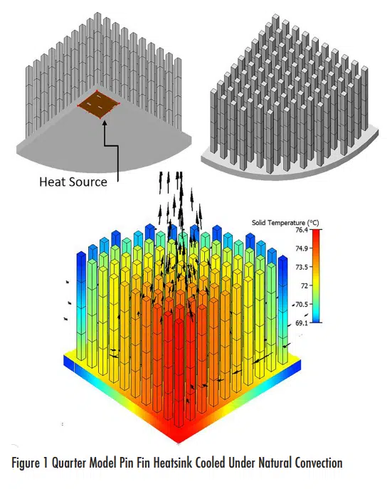
By way of an example to demonstrate this process, Figure 1 shows a quarter model of a circular base pin fin heatsink.
The heatsink cools a small centrally located heat source on the bottom of the base by natural convection. A full conjugate 3D CFD thermal simulation is conducted with 2 symmetry planes defined to represent the other 3 quarters of the heatsink. As expected, the central pins above the heat source are the hottest. Each of the pins is discretised into small rod elements. It is these small bodies that will either be removed or an identical part added to.
For this simple example, the addition and subtraction of bodies are constrained such that only the Thermal Bottleneck in the top tip bodies of each pin is considered. In this way, remodeling the heatsink only changes the height of each pin being varied: a 1D type remodeling.
The cost function is taken as the maximum heatsink temperature. This occurs at a location directly above the heat source and is directly proportional to the overall thermal resistance.
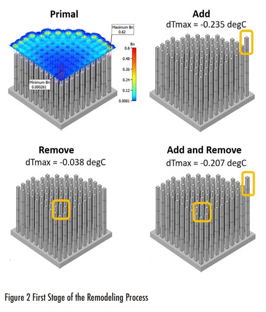
The first step in the remodeling process is shown in Figure 2. Despite the central pins being the hottest, their tips have the lowest Thermal Bottleneck. The highest Thermal Bottleneck is located on the tip of a peripheral pin. Three resulting models are simulated: one with a body added to the pin tip with the highest Thermal Bottleneck, a second one in which the body is removed from the pin tip with the lowest Thermal Bottleneck and, in the third, both an addition and a subtraction are made. All three decrease the temperature rise of the heatsink, but it is the addition case that leads to the biggest decrease in temperature rise. This, therefore, forms the base model of the next stage of an iterative process.
The process is then repeated until such time as no subsequent modifications result in a temperature rise decrease.
1D REMODELING EXAMPLE
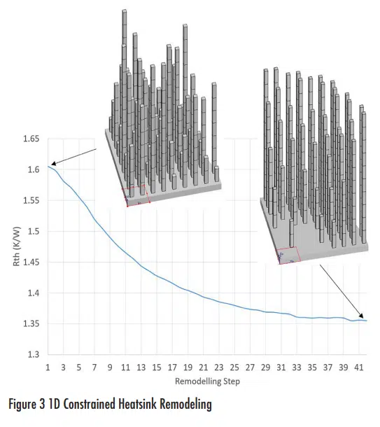
Using the same application as above, an initial heatsink to be remodeled has each pin defined at a random height from zero to a maximum design space height. This test was performed as part of an investigation into the sensitivity of the initial heatsink geometry to the final optimized state.
The optimal design (which was proven independent of the initial heatsink geometry) has the peripheral pins at a maximum design space height whilst the central pins above the heat source are all but removed. The heights of the pins increase between the center and the periphery.
The periphery of the heatsink has a larger area exposed to ambient, so the pin surface area benefits from maximizing there. It is much more difficult for the cool ambient air to penetrate into the central congested area of the heatsink, thus making the pins there redundant and leading to their being removed by the remodeling.
It could be argued that such a simple and constrained example could be parametrically defined (i.e. pin height) and optimized using more standard approaches. In this example, there are 60 pins and so there would be 60 degrees of freedom for the optimizer to consider. The Thermal Bottleneck-driven remodeling process identifies an optimum in only 41 steps using a physics-based approach as opposed to a purely numerical one.
2D REMODELING EXAMPLE
By controlling the discretisation of a heatsink geometry, extrudable, or at least prismatic geometries can be realized. Consider a standard plate fin extrusion. By discretising it into tessellated bodies that are the full (extruded) length of the heatsink, and only allowing for these full-length bodies to be removed or added to with similarly shaped full-length bodies, a resulting 2D profile can be maintained.
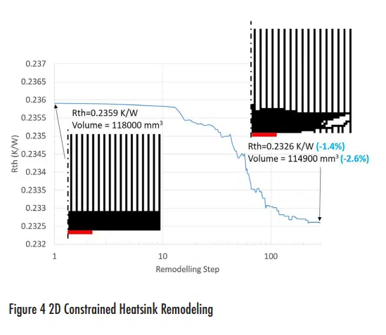
Figure 4 shows the remodeling process applied to the plate fin parametrically-defined heatsink. Again, symmetry is employed so as to only model half of the geometry. The heat source is centrally located on the base (red line in Figure 4). The heatsink is subjected to forced convection air cooling. The original heatsink is discretised into square section, full-length rods of the same dimension as the fin width.
The remodeling process results in a small improvement both in terms of thermal resistance and volume (mass). Specifically, additional surface area is achieved by carving out flow channels in the base, on the periphery away from the central heat source. The base does not need to be as thick in this region as it has less heat to spread. Removing some of its geometry so as to create new flow channels both reduces the mass and increases heat transfer area. It is noted that, despite their parametric simplicity, forced convection plate fin heatsinks are already surprisingly effective.
3D REMODELING EXAMPLE
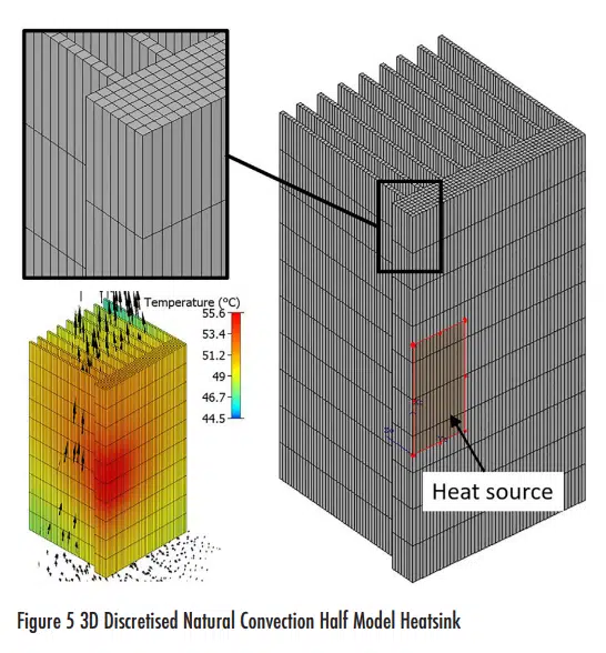
A heat sink can be discretised into a 3D collection of tessellated bodies such that for any location of the biggest Thermal Bottleneck body, a same-sized cuboidal body might be added to any of its air apparent faces. Similarly, any body might be removed allowing for holes to appear. For this example, a half model of a vertically oriented natural convection cooled heatsink is considered (Figure 5).
With a larger number of bodies comes a greater flexibility for novel topologies to emerge during the remodeling process. This, however, comes hand in hand with prolonged remodeling simulation times as many more steps are possible until an optimal design is identified.
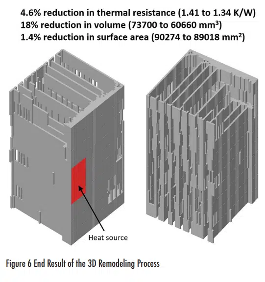
The resulting optimized heatsink generated by remodeling in 3 dimensions is shown in Figure 6. Whereas a modest 4.6% reduction in thermal resistance was seen, a more significant reduction in volume (mass) of 18% was achieved. There was only a 1.4% reduction in surface area though. In this case, the remodeling achieved a redistribution of extended surface area, bespoke to the cooling environment. The surface area at the downstream (top) part of the heatsink was redistributed to plates connecting to the tops of the fins. Also, the base at the top of the heatsink was carved out, with less effect on surface area but a greater effect on minimizing mass. It is also interesting to note the ‘frame’ type geometry that emerges with equally spaces gaps in some areas of the fins. While the bottom part of the heatsink is most efficient, as that is where the cooling ambient air enters, the top part is less efficient due to the preheating of the air as it passes up through the heatsink and so substantial remodeling occurred there. Although the resulting geometry proved to be more efficient than the original design, the somewhat coarse discretisation results in a stepped geometry. A more refined geometry would be generated by the remodeling process if the size of the discretised bodies had been smaller. It is envisioned that a post-processing smoothing stage would be applied to further refine the heatsink geometry in a similar manner to what is required to smooth out any numerical artifacts of some adjoint based topology optimizations. This would be done in addition to any other required changes identified by additive manufacture validation checks.
CONCLUSION
The opportunities that additive manufacturing provides have necessitated the new approach of ‘Generative Design’. Unconstrained by parametric topologies, and not reliant on legacy engineering expertise, approaches such as adjoint-based Topology Optimization and the remodeling method presented here will gain traction as additive manufacturing itself matures and becomes more cost effective.
REFERENCES
[1] R. Bornoff, B. Blackmore and J. Parry, “Heat sink design optimization using the thermal bottleneck concept,” 2011 27th Annual IEEE Semiconductor Thermal Measurement and Management Symposium, San Jose, CA, 2011, pp. 76-80, doi: 10.1109/STHERM.2011.5767181.

After receiving a bachelor’s degree in Mechanical Engineering in 1992 and a PhD for CFD research in 1996 from Brunel University in the UK, Robin joined Flomerics as a Flotherm support and application engineer. By the time of the acquisition of Flomerics by Mentor Graphics in 2008 he was the Product Marketing Manager for Flotherm. Now in Siemens Digital Industry Software, he is a Senior Key Expert in the Simulation and Test Solution division. With over 25 years’ experience in the field of electronics thermal simulation, he has published over 30 journal and conference papers and has had 7 patents granted

