A previous Electronics Cooling article, which discussed the process for analyzing the thermal performance of cooling fans [1], mentioned the need of accounting for the increasing coolant temperature as air passes through a heat sink. That article used an ‘average’ air temperature, which was defined as the midpoint between the inlet and outlet air temperatures. This article discusses that approach, as well as an alternate method that is more physically robust.
When a system is cooled with a fluid, the fluid temperature rises as it passes through the system and absorbs energy through convective heat transfer. The larger the power dissipation or smaller the mass flow rate, the greater the rise in coolant temperature. As the coolant temperature increases, a higher surface temperature is needed to dissipate the same power with the same convection coefficient. This increases the overall thermal resistance compared to a system in which the fluid temperature remains constant.
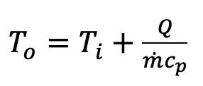
One method of accounting for this ‘advective’ thermal resistance is to assume that the average coolant temperature is the midpoint between the inlet and outlet coolant temperatures. As long as the cooling fluid remains single phase (i.e., no boiling), the outlet coolant temperature, To, depends on the inlet fluid temperature (Ti), the fluid’s specific heat (cp), the coolant flow rate (ṁ), and the power dissipation (Q) as shown in Equation 1.
If we assume that the representative coolant temperature is the midpoint between the inlet and outlet temperature (Tmid) = (To + Ti)/2, we can analyze the convective heat transfer to determine the temperature of the heat transfer surface (Tsurface), which is assumed to be uniform, using Equation 2.
While this approach to account for the coolant temperature rise is often quite accurate, it is an approximation because it assumes that the average coolant temperature is the same as the midpoint value. One can recognize the limitation of this assumption by considering a situation in which a coolant enters a tube that has a constant surface temperature. If the tube is only a meter long, it may be reasonable to assume that the appropriate typical temperature of the coolant as it flows past the tube surface is close to the midpoint temperature. However, if that same uniform-temperature tube is 10km long, it is likely that the fluid would essentially be at the tube temperature well before the end of the tube and, therefore, the average fluid temperature would be closer to the tube surface temperature. The accuracy of the midpoint temperature assumption shown in Equation 2 depends on a combination of the mass flow of fluid and the convective thermal resistance (heat transfer coefficient and amount of heat transfer area).
A more general approach to account for the advective thermal resistance is to turn to methods developed for fluid-to-fluid heat exchangers. The effectiveness-NTU method relates the effectiveness of a heat exchanger, ε, to the number of thermal units (NTU). The effectiveness, which is defined as the actual heat transfer between fluids divided by the maximum possible heat transfer between fluids, i.e., ε = qactual ⁄ qmaximum possible, is a function of the heat exchanger configuration and the flow rates and specific heats of the two fluids. The NTU for a system is defined as NTU = UA ⁄ (ṁcp)minimum , where ṁcp is the fluid mass flow rate times its specific heat; the ‘minimum’ subscript indicates that the fluid with the smaller value of ṁcp is used to calculate NTU. The term UA is the inverse of the overall thermal resistance between the two fluids, including convection coefficients for both fluids, fin efficiencies, and conduction through the solid materials that separate the two fluids.
A number of relatively complex equations have been developed to calculate the effectiveness of heat exchanges with different geometries, configurations, etc. Fortunately for those of us who work in the area of electronics cooling, we generally do not need to deal with them. When there is only a single fluid involved, the effectiveness is simply ε=1– e–NTU. This equation allows us to easily account for the effect of advective thermal resistance to determine the heat transfer from a surface, which is assumed to be at a uniform temperature, to a fluid with a known inlet temperature. The UA term in the NTU calculation is the inverse of the thermal resistance, Rthermal = 1/hA, where h is the convection coefficient and A is the effective surface area that accounts for fin efficiency.
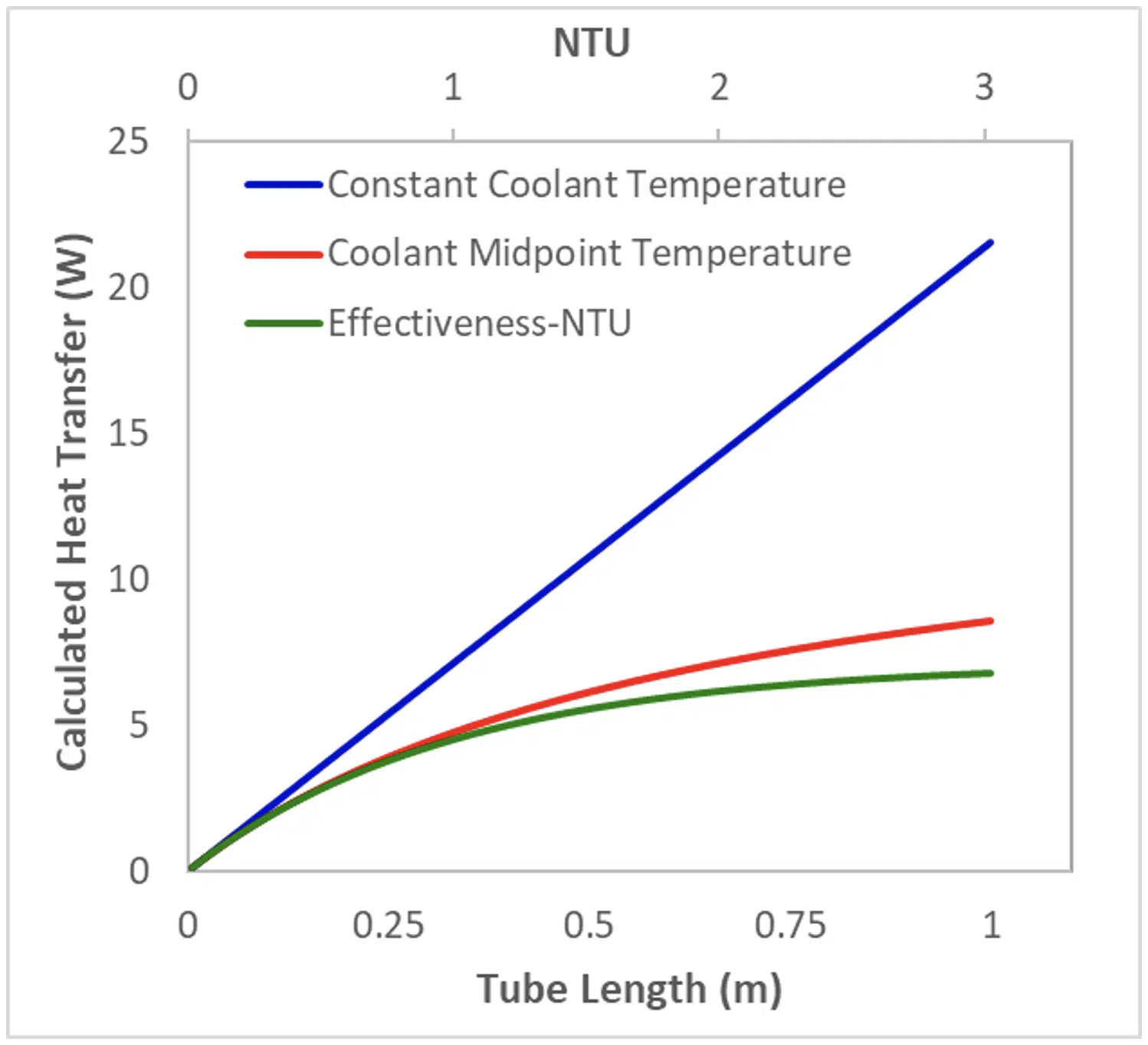
Consider, for example, a 10 cm diameter tube that is held a fixed temperature of 100°C. Air at atmospheric pressure enters the tube at 25°C and an average velocity of 1 m/s. Ignoring the effects of developing flow, the convection coefficient is constant so the heat transfer to the air is only dependent on the tube length, which dictates the area available for heat transfer. Figure 1 shows the heat transfer calculated for this situation using three different assumptions on the coolant temperature (the equations that were used for these calculations are summarized in Table 1 later in this article). For ‘Constant Coolant Temperature’, it is assumed that the cooling air temperature is the inlet air temperature throughout the tube. For ‘Coolant Midpoint Temperature’ the average coolant temperature is assumed to be the midpoint of the inlet and outlet coolant temperatures (using Equation 2). The ‘Effectiveness-NTU’ results correspond to using the heat exchanger ε-NTU approach for calculating the heat transfer. This figure also shows the values of NTU calculated for the conditions considered in this analysis.
Figure 1. Calculated heat transfer to air flowing through a tube
Figure 1 shows that at low enough values of NTU, which may be due to high thermal resistance (in this case, a short tube with relatively small heat transfer area) or large mass flow rates, all three approaches predict similar values for heat transfer. But as the length of the tube increases (the NTU becomes larger), there is substantial error associated with assuming the coolant temperature remains constant. Eventually, at a large enough NTU the midpoint temperature assumption also demonstrates increasing error. Physically it is logical that the heat transfer would eventually asymptote to a fixed value as the tube becomes long enough and the coolant temperature approaches the wall temperature; this behavior is only demonstrated by the calculations using the Effectiveness-NTU method.
One can estimate when and whether the effectiveness-NTU method is needed for an accurate calculation by comparing the heat transfer calculated with the other methods to that calculated using ε-NTU. Defining the calculation error as E = (Q-Qε-NTU)/ Qε-NTU, the error associated with assuming constant coolant temperature is:
where Rth is the heat sink thermal resistance and NTU = (hA)/ ( ṁcp) = 1/( Rth ṁcp).
Likewise, the error associated with using the midpoint coolant temperature can be calculated using:
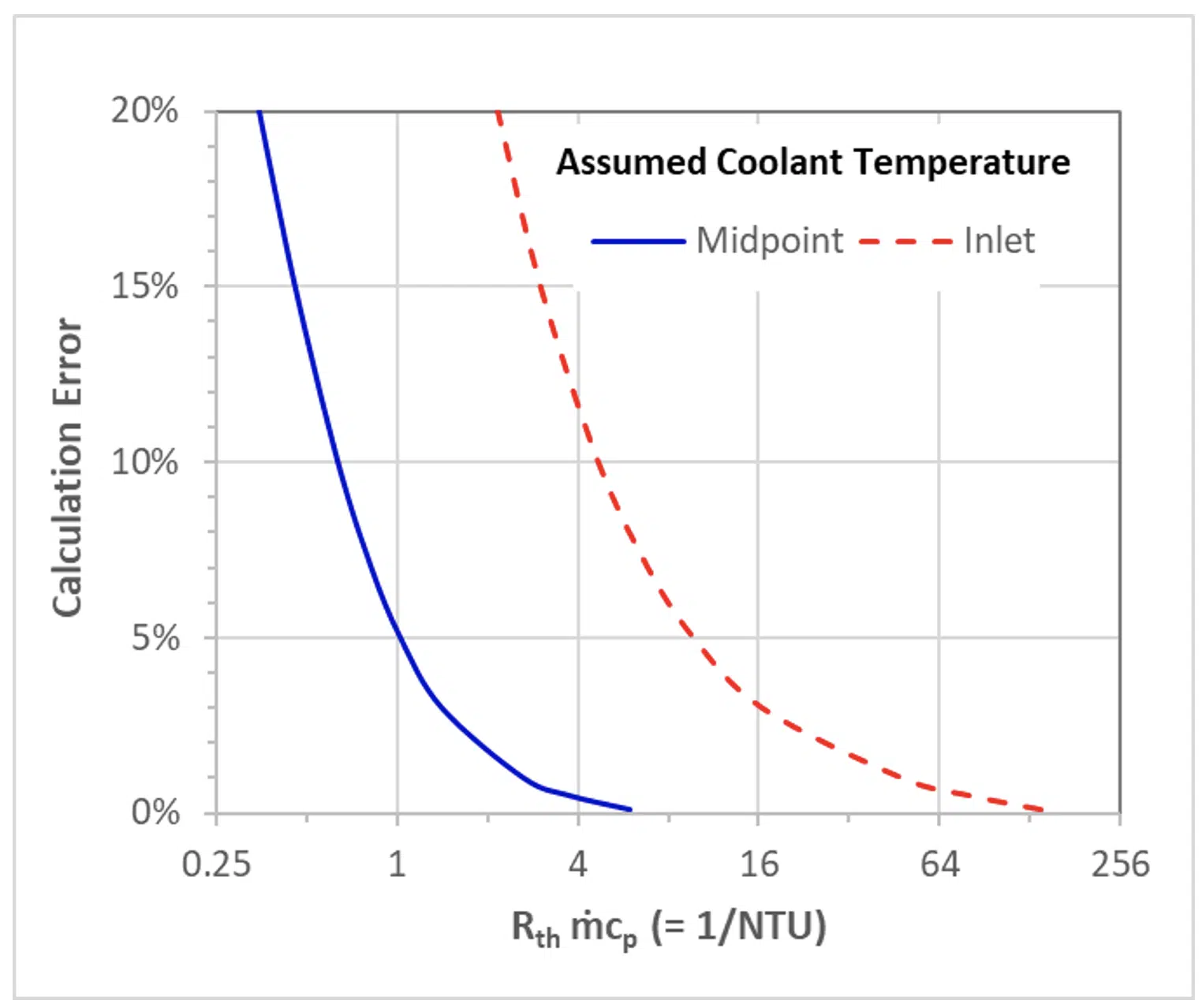
These two error values are plotted in Figure 2. This shows, that at a high enough flow rate or thermal resistance, one can assume that the flow rate temperature is either fixed or equal to the midpoint temperature. However, at low flow rates, those assumptions can lead to significant errors.
Figure 2. Comparing errors of different assumptions for coolant temperature
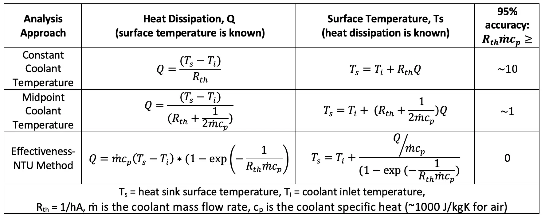
Table 1 summarizes the equations that can be used to determine the heat transfer (for a known heat sink surface temperature) or the heat sink temperature (for a known heat dissipation) with different approaches to account for the advective thermal resistance. This table also shows what inverse NTU (thermal resistance multiplied by the coolant mass flow rate times its specific heat) at which the calculation would be within ~5% of the correct value calculated using the NTU-Effectiveness method.
Table 1. Heat transfer & surface temperature equations for different advective thermal resistance approaches
Summary
This article described approaches that can be used to account for the additional thermal resistance due to the coolant temperature increasing as it passes through the system it is cooling. The magnitude of this effect depends on the coolant properties (specific heat), its flow rate, and the thermal resistance of the system it is cooling. At low flow rates or high thermal resistance, it is acceptable to assume that the coolant temperature remains constant or to use the midpoint coolant temperature. However, the NTU-Effectiveness approach that was described here should be applicable to any situation.
References
1. Ross Wilcoxon and Genevieve Martin, “Fan Cooling – Part 1: Determining Flow Rate”, Electronics Cooling Magazine, Spring 2021, pp. 6-9
