Near the end of the 20th century, increasing power levels became the primary challenge in system design, which triggered a complex response from electrical, mechanical and material engineers. The combination of thermal measurements and thermal simulation helped achieve thermally aware system designs. However, no real solution was known for the valid comparison of thermal design concepts and for identifying failure locations in actual samples during quality control. Simulation attempts often failed because the thermal material parameters from data sheets significantly differed from the actual behaviour of thin material layers which typically build up power packages and modules.
Breakthroughs often occur all of a sudden. In the 1980’s, Professor Vladimír Székely studied a set of measurements of the temperature change in time of an assembly after applying a sharp power step on it. Three samples of the same manufacturing lot were tested.
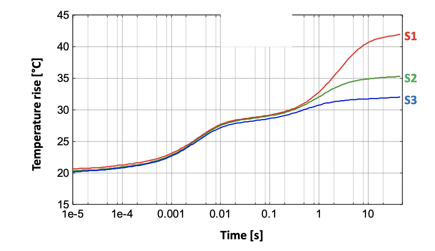
It was obvious in this plot (Figure 1) that, for the first ~ half second the heat still propagated in the internal sandwich-like structure of the sample, through the silicon chip, on which power was applied, then through various layers of the investigated packaged device. After this half a second, the heat penetrated into the thermal paste (thermal interface layer, TIM) between the sample and the test bench. The screws that provided the fixing force to the sample were not tightened equally, leading to different thicknesses of the thermal paste in the three cases. Structural changes caused a difference in the thermal transient behaviour.
Figure 1. Temperature change on three samples of the same manufacturing lot after applying a sharp power step
It has long been known that, in thermal measurements, a very stable measurement arrangement must be ensured in order to achieve repeatability. Changes in the structure of the arrangement induce changes in the temperature response. In a conventional interpretation of the data, the measurement of sample S3 in Figure 1 is good while the two other measurements are wrong. However, in considering the results differently, the dissimilarity in the measurement results is not considered to be the problem but is instead the solution needed for addressing the problems of measurement repeatability, as outlined above.
Figure 2. Convolution in space (blurring) and deconvolution to restore the original picture
V. Székely was an expert on the theory of filters and a renowned authority on image processing techniques. He knew how smudged pictures can be restored to original sharpness. A defocused camera causes a blurring of pictures, that is, the content of a pixel is superposed on the neighbouring pixels by a certain weight. This is operation is known as convolution in space, a two-dimensional filter smashes the picture content over the image (Figure 2 a to b).
The process is a linear transformation; it can be reversed by a deconvolution procedure (Figure 2 b to c). The theory of linear systems provides several algorithms for this operation, such as Fourier transform or iterative methods.
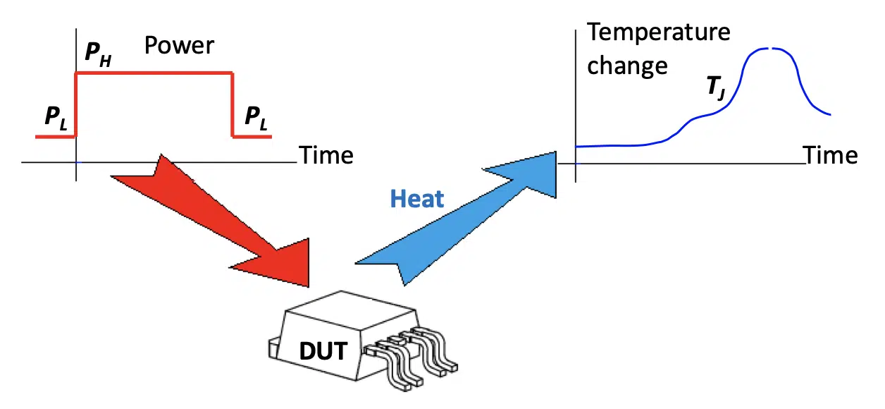
Prof. Székely realized that the bumpy response curve of the device under test and the measurement environment is the convolved signal of the sharp power step, at the output of a low pass filter [1].
Figure 3. The scheme of thermal transient testing, sharp power changes in time produce a characteristic bumpy temperature change curve.picture
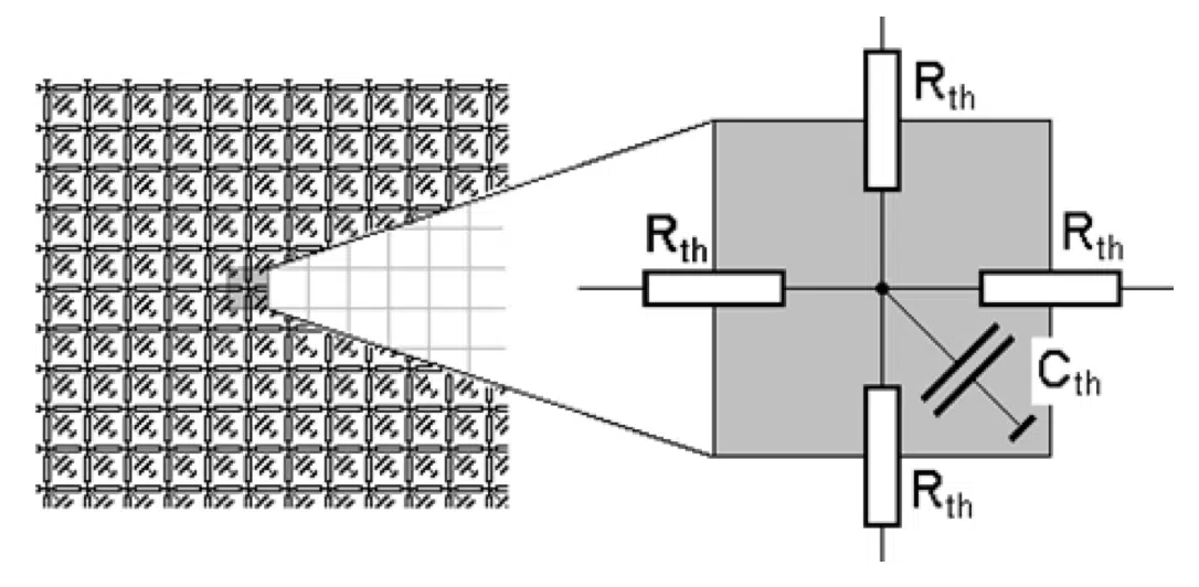
The different layers in the structure have various geometries and thermal parameters, such as thermal conductivity and specific heat. These can be represented by a dense net of thermal resistances and thermal capacitances, with one or more entry points of the heat (driving points) (Figure 4). Thermal capacitances cause a delay in the temperature increase because they can temporarily store the thermal energy.
In Figure 2, a known filter (the aperture of the defocused optics) blurred the picture. The same known filter can be used to restore the original from the convolved, blurred one in a reverse process. For the convolution in time, which produces the bumpy curve at the output of a thermal resistance-capacitance (RC) network, the players in the scheme are again: an input signal, a filter and a convolved output signal. However, the target is now different: in the deconvolution scheme, the filter is the unknown that must be determined:
- from the known input signal: the waveform of the applied power step and
- from the output signal: the measured temperature change.
Some measurement apparatus is needed to apply the power and to record the temperature change, but no external source (x-ray or acoustic) is needed for the investigation. The structure of an assembly can be identified using the inherent temperature changes in the system.
Figure 4. Equivalent thermal RC net of an object characterized by its geometry and its thermal resistances and thermal capacitances
Although the convolution theory and the use of RC filters seem to be distant from the practical discipline of thermal transient testing, it is easy to find a common denominator between them: the theory of linear systems. In the typical temperature range of use, most non-linear effects (radiation, nonlinearity of thermal conductivity) can be neglected.
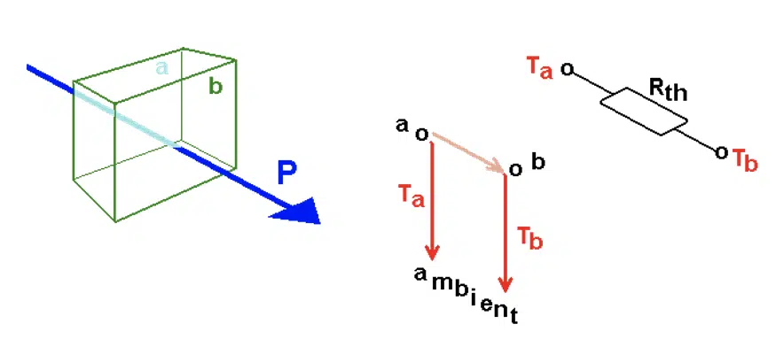
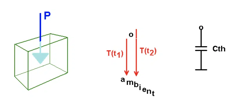
Thermal conduction is dominated by a blend of two mechanisms, heat propagation through an elementary slice (Figure 5) and internal energy growth due to heat flow into the slice (Figure 6).
Figure 5. Heat flow through a material slice
Figure 6. Heat flow into a material slice
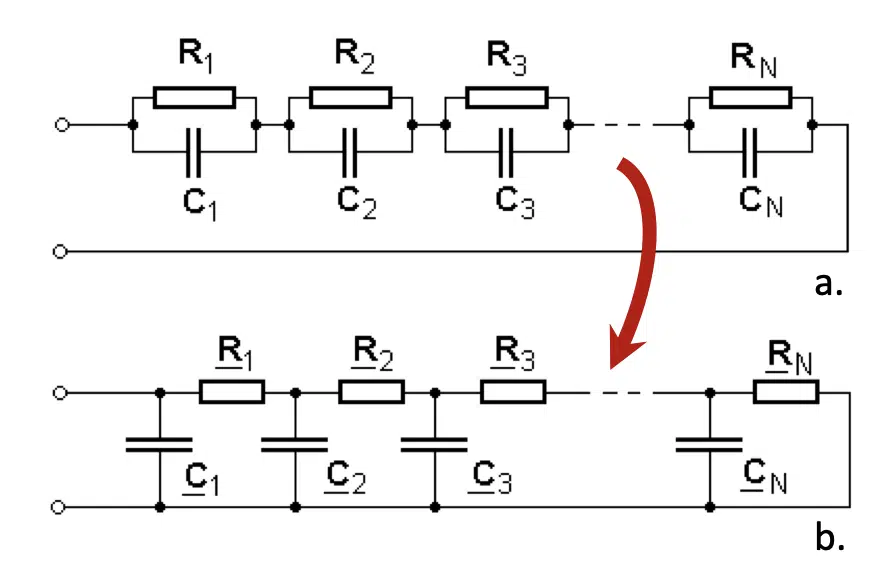
The theory of linear systems claims that the system corresponding to Figure 4 behaves in the same way as a reduced set of thermal resistances and capacitances arranged in one of the configurations shown in Figure 7.
Figure 7. Foster (a.) and Cauer (b.) type filter representation of discretized structures
Actual thermal systems correspond to the complex RC net of Figure 4. In a test, P(t) power is applied at some thermally connected nodes and terminated by constant temperature at their boundaries. In case constant Pon power is switched on at zero-time (step function), a single series RC element in Figure 7a will produce exponential temperature increase after switching on the power (current), adding T(t) = Pon •R•(1 – e – t/τ) temperature (voltage) term to the chain response. The R magnitude denotes the thermal resistance of the fragment; τ =R•C is a time constant where C is the thermal capacitance. Accordingly, at the input (in this case at the junction) we get a sum of exponential functions,
Different material slices have different characteristic thermal parameters, the resulting different R magnitudes and τ time constants make the T(t) curve “bumpy”, as seen in Figure 1.
In a fine net of series RC chain stages, Equation (1) approximates an integral
The formula says that the system response is the convolution-like integral of an R(τ) time constant spectrum and a fixed f(t)=1 – e– t/τ function. The inverse of (2) can be produced in an iterative numerical process. The mathematical apparatus of such a deconvolution procedure yielding R(τ) is rather complex; a rigorous treatment of it is described in [2]. The procedure is called Network Identification by Deconvolution, NID method.
Figure 8. Time constants in a lumped element system (a) and in a distributed parameter system (b)
Before the advent of the NID method, the measured curved could be approximated by 3-4 time constants that can be determined with curve fitting. The NID method easily yields several hundred RC stages and produces a fine resolution equivalent scheme of the structure.
Discrete time constants (Figure 8a) or their spectrum (Figure 8b) can be produced with this process from a measured T(t) curve, but the equivalent RC network corresponds to Figure 7a, which is a behavioural model only.
In the physical reality, Figure 5 illustrates the temperature drop across a material slice. In Figure 6, T1 and T2 temperatures are measured from the ambient, a Cth thermal capacitance appears between a point representing the material portion and the ambient.
Serial RC chains (Figure 7a) can be converted to RC ladders (Figure 7b) by the Foster – Cauer transformation known in linear circuit theory (see e.g., Annex C in [3]). These two processes (the exponential decomposition by deconvolution and the Foster – Cauer transformation in a sequence), provide a direct synthesis method for transforming measured transients into a one-dimensional physical compact model of the complex thermal system.
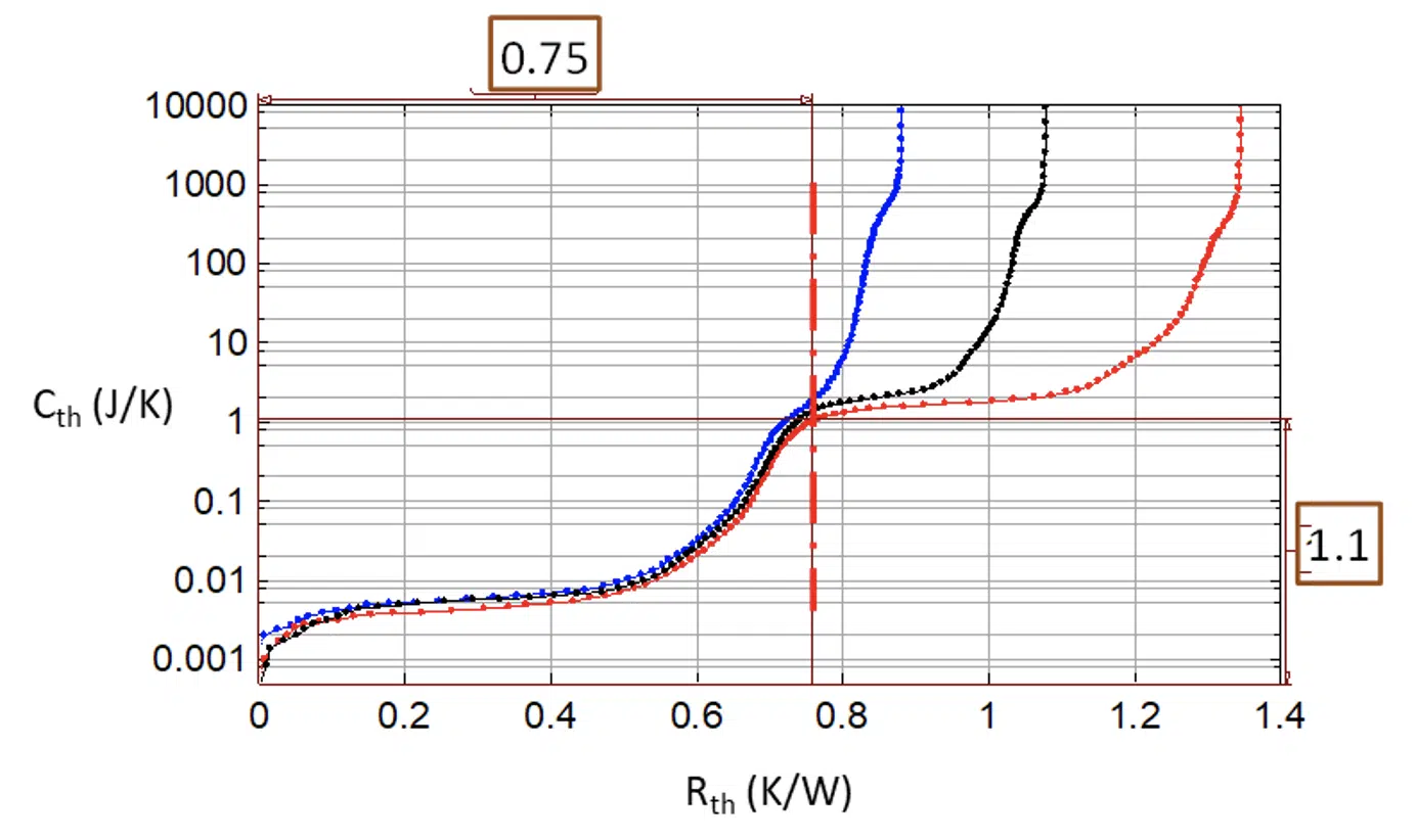
The structure function (Figure 9) is an excellent graphic tool to characterise the heat conducting path. In the ladder of Figure 9b this chart sums up the thermal resistances, starting from the heat source (junction) along the x-axis and the thermal capacitances along the y-axis.
A low gradient section in the structure function means that, at the corresponding structural detail, even a small volume such as a thin material layer that has low thermal capacitance causes large change in thermal resistance. These regions have low thermal conductivity or small cross-sectional area.
Figure 9. Structure function: the graphic representation of the thermal RC equivalent of the system
Steep sections of the function correspond to material regions of high thermal conductivity, because a huge amount of matter represents tiny additional thermal resistance only. These are typically metals; the steepness also may indicate large cross-sectional area. Sudden breaks in the slope indicate material or geometry changes.
Consequently:
- Thermal resistance and capacitance values of details in an assembly can be measured based on the temperature response on a single power step. In this way structure function methodology can be used for device characterization or failure analysis.
- When geometrical dimensions are known, heat transfer coefficients and specific heat values can be directly determined from the structure functions, either in-situ, in a real system or in its mock-up.
- Moreover, in instruments where the thickness of samples can be controlled or at least determined, thermal parameters of material layers or sheets can be measured, as the function of thickness and pressure.
Figure 10 shows the structure functions converted from the temperature transients of Figure 1. The internal layers of different quality can be observed, and also the flat plateau corresponding to the thermal paste after the divergence point at 0.75 K/W and 1.1 J/K.
In structure functions, many details of an actual assembly can be distinguished along with their partial thermal resistance and capacitance values. However, it should be noted that the structure function analysis is not a fully automated (“black box”) technique.
There are three ways to assign actual assembly components to sections in the structure function. These are:
- The manufacturer of the device may know all internal geometries and material parameters. In such a way, a “synthetic” structure function can be built up by, for example, superposing slices of material with given thermal resistance and capacitance in a spreadsheet tool, and comparing the measured structure functions to it.
- An approximate model can be built up in a finite element or a finite difference simulation tool. Thermal transients can be simulated in the tool and structure functions can be composed of those. Geometry and material parameters can be fine-tuned until the simulated and measured structure functions match.
- Measured structure functions can be compared to an already identified “golden device”. This technique is advantageous in production control.
Figure 10. Structure functions of the three samples of the same manufacturing lot and the test bench
In this short overview of the origin of structure functions and their possible use in thermal transient measurements and simulations, we intended to draw the attention of thermal engineers to the growing importance of thermal transient testing. We hope that we succeeded to raise the awareness of the readers towards this very important method. Use cases and application fields can be found in the papers listed in the references and in other related publications of the authors.
REFERENCES
[1] https://en.wikipedia.org/wiki/Convolution, acessed 15-MAY-2021
[2] V.Szekely: “Identification of RC networks by deconvolution: Chances and Limits”, IEEE Trans. On Circuits and Systems – I: Fundamental Theory and Applications, Vol.45, No.3, pp.244-258, 1998. DOI: 10.1109/81.662698
[3] JEDEC Standard JESD51-14, “Transient Dual Interface Test Method for the Measurement of Thermal Resistance Junction-to-Case of Semiconductor Devices with Heat Flow through a Single Path” (November 2010) Available online: http://www.jedec.org/sites/default/files/docs/JESD51-14_1.pdf (accessed on 13 January 2021).
[4] D. Schweitzer, H. Pape, L. Chen: “Transient Measurement of the Junction-To-Case Thermal Resistance Using Structure Functions: Chances and Limits”, Proc. 24th SEMITHERM, San Jose, CA, 2008, DOI: 10.1109/STHERM.2008.4509389
[5] Katsuaki Suganuma (editor) : “ Wide Bandgap Power Semiconductor Packaging”, 1st Edition (Materials, Components, and Reliability), eBook ISBN: 9780081020951, Paperback ISBN: 9780081020944, Woodhead Publishing, May 2018
[6] P. Szabo; O. Steffens; M. Lenz; G. Farkas: “Transient junction-to-case thermal resistance measurement methodology of high accuracy and high repeatability”, IEEE Trans. on Components and Packaging Technologies , 2005, Vol. 28, Issue: 4 pp: 630-636
