Introduction
Stringent greenhouse gas-emission legislations have accelerated the electrification of ground and air transportation. Since the electric motor is one of the core components of the electric drivetrain, improving its performance is a key enabler to better performance metrics of an electric drivetrain, i.e., higher power and torque density, better fuel economy (lower $/mile), and overall drivetrain efficiency. Permanent magnet synchronous motors (PMSM) are broadly used in traction powertrains because of their high power, torque density, and efficiency. However, high heat generation rates in PMSM as a consequence of electromagnetic (EM) losses often limit motor efficiency and longevity by aging the winding wire insulation and premature demagnetization of the magnets. Therefore, proper quantification of heat generation in electric motors and advanced embedded motor cooling techniques remain topics of immense interest. In this article, we discuss an efficient two-way coupled EM and thermal modeling framework for electric motors. By utilizing the developed modeling framework, we present two advanced thermal management techniques, namely embedded circular cooling channel within the stator core and direct winding heat exchanger (DWHX), and emphasize their impact on peak temperature and thermal performance of an electric motor.
For low power electric machines, air cooling is typically used, whereas high power density electric motors typically require liquid cooling to tackle high heat loads [1]. Typically, in automotive and industrial machines, closed-loop liquid cooling via an external cooling jacket around the motor stator is employed [2]. However, jacket cooling (JC) technology often suffers from poor heat extraction from the windings to the external coolant because of the high overall thermal resistance between the windings and the coolant.
In contrast to jacket cooling, which is employed externally to the stator, cooling channels can be employed in the stator and rotor cores. This cooling technique has been adopted by multiple industries. For example, Rolls Royce implemented circular channels to the stator core of a PMSM motor [3], while Siemens AG also designed stator cooling channels adjacent to the windings for high power generators [4]. Rectangular channels were implemented for cooling the Tesla Model 3 motor [5]. However, cooling channels embedded within stator laminations can alter the magnetic flux path by imposing extra reluctance. To overcome the limitations of the aforementioned cooling techniques, Semidey and Mayor [6] proposed a water-cooled direct winding heat exchanger (DWHX) concept to extract heat directly from the windings. DWHX dramatically reduces the thermal resistances between the winding and the coolant, and hence significantly higher current density can be achieved while operating within the insulation’s thermal limit.
Building an experimental setup and performing experiments based on the analytical expressions for advanced cooling design and sizing are not economically viable and cannot guarantee optimal cooling performance. Therefore, numerical simulations can play a critical role in the early stage of the co-design of electric motors. Typically, lumped parameter thermal network (LPTN) and computational fluid dynamics/heat transfer (CFD/HT) are used for electric motor thermal performance analysis. Although EM and thermal performance of electric machines are strongly dependent on each other, most of the previous studies have not considered the effects of the cooling strategy on EM performance because of the high computational cost. Therefore, there is a need for an efficiently coupled EM and thermal simulation technique.
Results and Discussion
In this article, we present a two-way coupled EM and CFD/HT modeling framework to characterize the overall performance of a jacket-cooled BMW i3 motor. Figure 1 illustrates the front view of a conventional jacket-cooled BMW i3 motor having a slot/pole ratio of 72/12. The stator lamination diameter, stator bore, slot depth, shaft diameter, and axial lamination length are 240.9 mm, 179.8 mm, 21.5 mm, 60.0 mm, and 130.0 mm, respectively. To reduce the computational cost, a single rotor pole and the corresponding stator configuration have been considered as the computational domain for the EM and 3D CFD/HT simulations by realizing angular and axial symmetry (see Fig. 1 (b-c)). Additionally, thermal contact resistances and radiation heat transfer has been neglected in the CFD/HT model, and liquid cooling has been simulated as a convective boundary condition on the stator outer surfaces.
Figure 1: (a) Front view of a 125kW BMW i3 motor and computational domain for (b) 2D electro-magnetic and (c) 3D CFD/HT simulation.
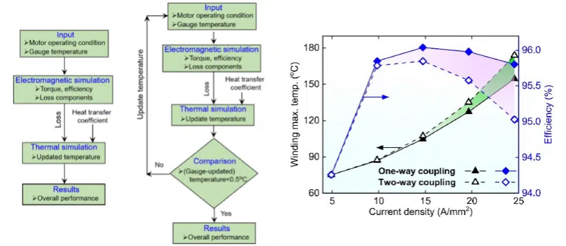
Figure 2 (a) and (b) outline the one-way and two-way coupled EM and thermal modeling frameworks. In the conventional one-way coupled algorithm, EM losses are calculated using pre-defined temperatures. Afterwards, all calculated losses are transferred to the CFD/HT model to compute motor temperatures for the pre-defined heat transfer coefficient. In contrast, in the two-way coupled framework, motor temperatures calculated from the CFD/HT model are fed back to the EM model. Motor loss components are then recalculated using the updated temperatures. Since EM and CFD/HT models are linked via the motor temperatures, iterations have been carried out until the maximum temperature difference between volume average temperature of the winding/stator/rotor/magnet at i+1th and ith iteration are less than 0.5oC [7].
Figure 2: (a) One-way and (b) two-way coupling framework for EM/thermal modeling, (c) Comparison between one and two-way coupling algorithm as a function of current density while maintaining a constant speed of 4,500 rpm and convection heat transfer coefficient of 5,000 W/m2K.
Figure 2 (c) presents the comparison between one and two-way coupled EM and thermal modeling algorithms. At higher current density, the one-way coupling algorithm under-predicts the winding temperature and consequently over-predicts the motor efficiency, compared to the two-way coupling algorithm. The two-way coupling algorithm accounts for increases in the motor temperature, which adversely affect the winding resistance and magnetic flux. These eventually increase copper and core losses, and resulting in higher winding temperature and lower efficiency.
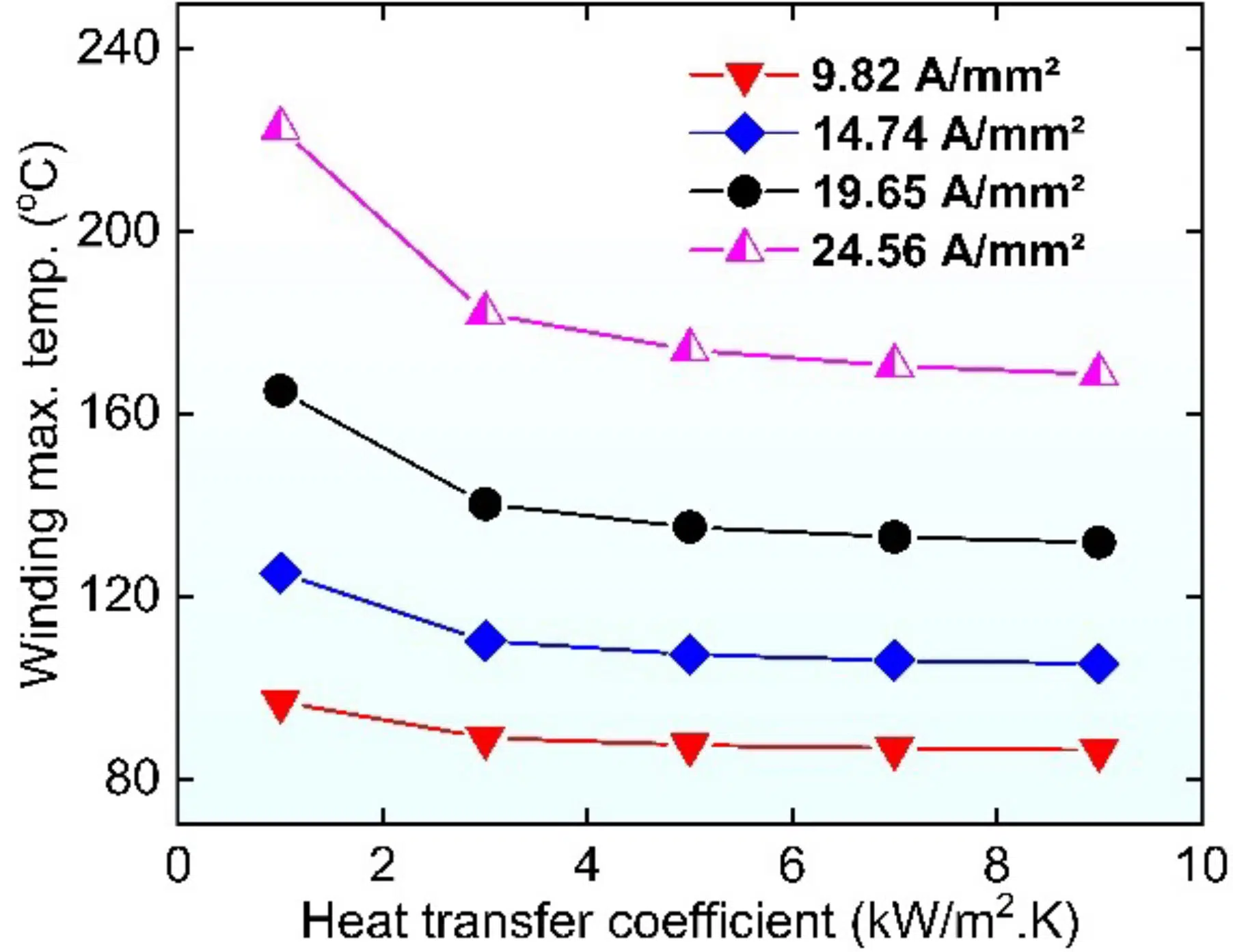
Figure 3: Maximum winding temperature vs. convection heat transfer coefficient for different current densities, while maintaining a constant shaft speed of 4,500 rpm and considering 70oC as constant fluid temperature.
To assess the effect of convective resistance in the case of jacket cooling, we conducted a parametric study of coolant flow rate through the jacket housing/heat transfer coefficient at the stator outer wall. Fig. 3 shows that winding temperature gradually reduces as the heat transfer coefficient increases, especially at higher current densities. This can be attributed to the reduced convective resistance between the motor housing and coolant as the heat transfer coefficient increases. However, beyond a threshold value of heat transfer coefficient of ~5,000 W/m2K, the temperature slope flattens, indicating conduction resistance dominance. In other words, beyond that threshold value of the heat transfer coefficient, motor thermal performance is mainly determined by the conduction resistance between the heat source, i.e., the winding slot and the coolant. Therefore, in order to further enhance the thermal performance of the electric machine, conduction resistance between the winding and the coolant must be reduced.
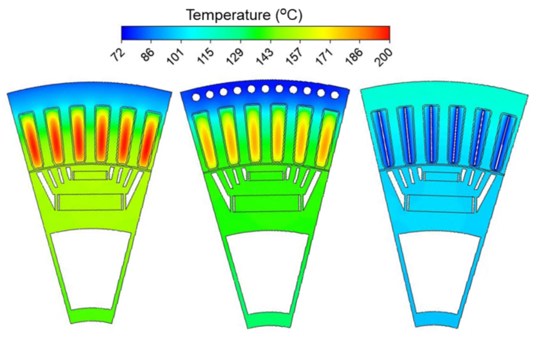
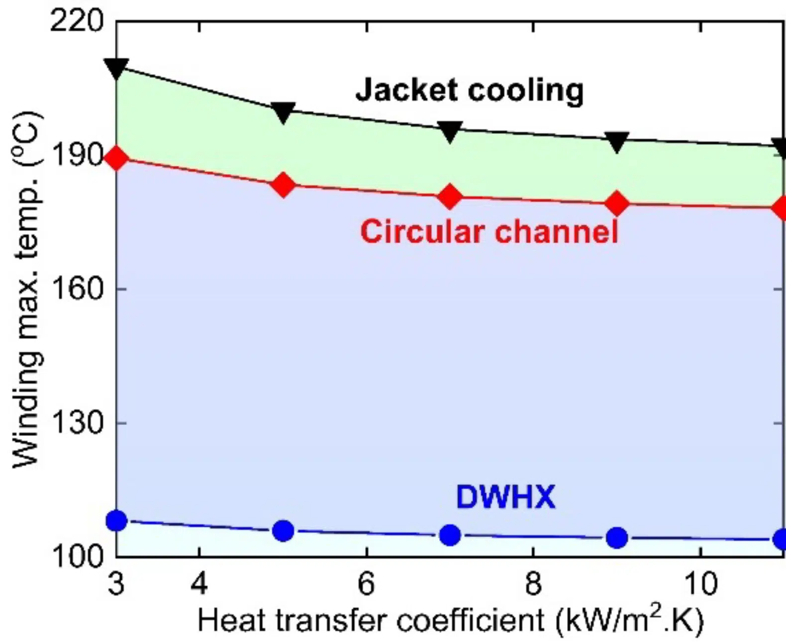
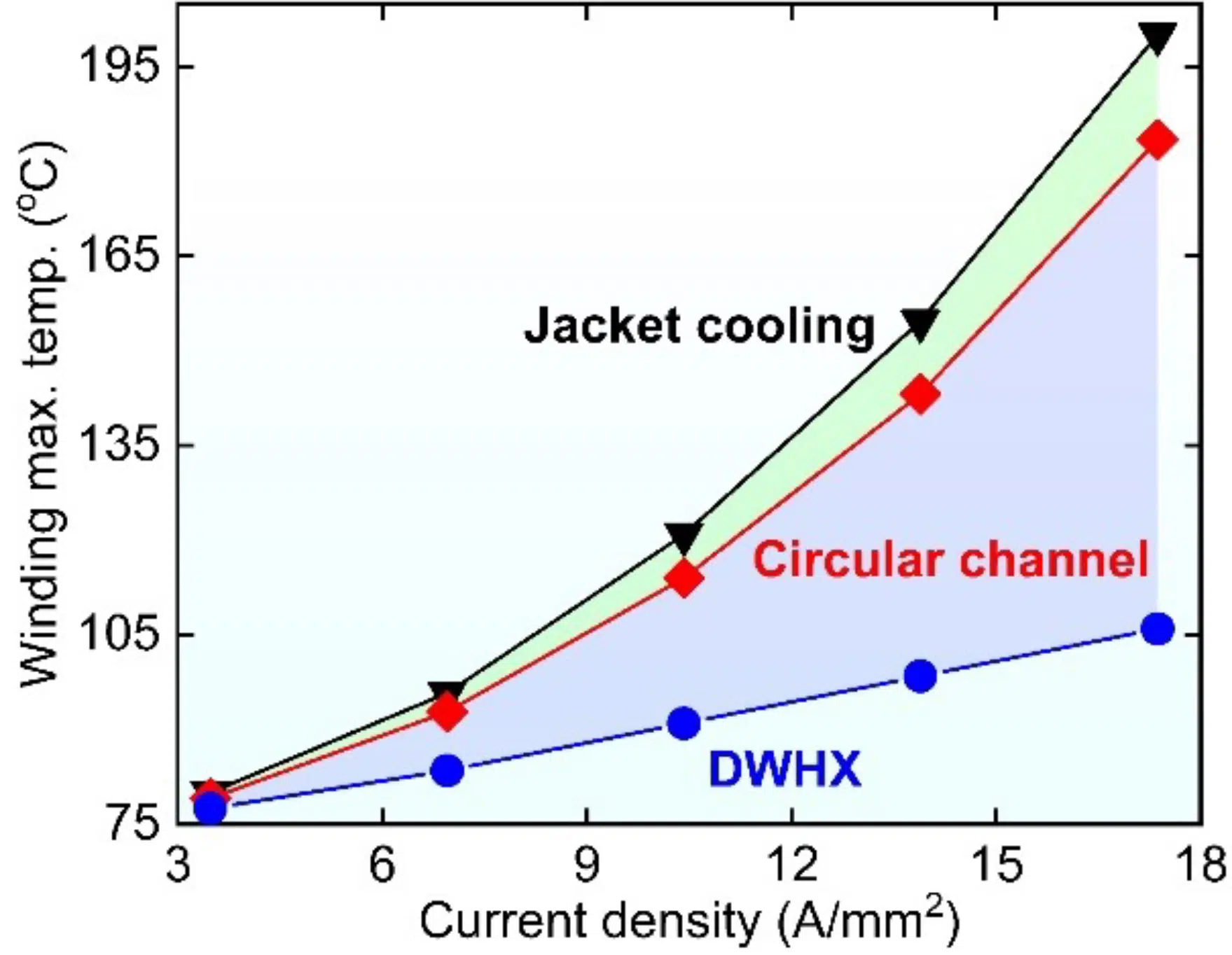
We used a two-way coupled EM and thermal modeling framework to analyze the effect of implementing circular cooling channels in the stator lamination of a BMW i3 motor (see Fig. 4 (b)) to directly extract heat from the stator yoke. By integrating cooling channels in the stator back iron, conduction thermal resistance can be significantly reduced by shortening the distance between the windings and coolant. This significantly enhances the thermal performance (see Fig. 4 (b)) compared to the jacket cooling. At a higher electrical loading of 17.37 A/mm2, the circular channels provide significant benefit over jacket cooling, e.g., 14-20°C lower peak temperature for a heat transfer coefficient in the range of 3,000-11,000 W/m2K (see Fig. 5). However, directly incorporating cooling channels in the stator may saturate the stator core by introducing additional magnetic flux resistance [8].
The thermal resistance between windings and coolant can be significantly reduced by employing DWHX in the stator slots, as shown in Fig. 4 (c). The DWHX technique transfers the winding heat loss directly into the coolant, resulting in a significant reduction of the winding-coolant thermal resistance and uniform temperature distribution compared to other cooling techniques (see Fig. 4 (c)). For example, by employing DWHX, motor peak temperature can be reduced by ~88-102°C compared to jacket cooling, as shown in Fig. 5. Therefore, the integration of DWHX provides a substantial increase in current density within the allowable thermal limit without compromising the thermal integrity. However, a careful design is required to apply DWHX technology in a distributed wound machine and to maintain a high copper fill factor.
Figure 4: Temperature distributions of (a) jacket cooled, (b) circular channel, and (c) DWHX cooled motor at 4,500 rpm, 17.37 A/mm2 current density, 45 EDeg phase advance, and heat transfer coefficient of 5,000 W/m2.K.
Figure 5: (a) Peak temperature vs heat transfer coefficients at current density of 17.37 A/mm2, and b) peak temperature vs current density at heat transfer coefficient of 5,000 W/m2.K. For all simulations, motor speed and phase advance were set at 4,500 rpm, and 45 EDeg.
Conclusions
Since EM and thermal performances of electric motor are dependent on each other, two-way coupled EM-thermal modeling framework can be utilized in the early stage EM design of the electric motor. Although single-phase DWHX can significantly reduce the conduction resistance between the winding and the coolant and offer high current density, DWHX cooling may not be sufficient for next-generation electric ground and air transportation. For ultra-high power density motors, the resistance between the winding and the coolant needs to be eliminated by placing the coolant in direct contact with the winding or by taking advantage of phase-change cooling.
References
[1] M. Popescu, D. A. Staton, A. Boglietti, A. Cavagnino, D. Hawkins, and J. Goss, “Modern Heat Extraction Systems for Power Traction Machines—A Review,” IEEE Transactions on Industry Applications, vol. 52, no. 3, pp. 2167-2175, 2016.
[2] F. JinXin, Z. ChengNing, W. ZhiFu, and E. G. Strangas, “Thermal analysis of water cooled surface mount permanent magnet electric motor for electric vehicle,” in 2010 International Conference on Electrical Machines and Systems, 2010, pp. 1024-1028.
[3] A. J. Mitcham and A. G. Razzell, “Stator Core”. Patent 7288870B2, 30 October 2007.
[4] H. Stiesdal, “Generator with a stator comprising cooling channels and method for cooling a laminated stator of a generator”. Spain Patent 2415661T3, 26 July 2013.
[5] S. Munro, “Tearing Down Tesla Segment 8: Comparing the Cooling Strategy / Housings of Motors for Tesla Model 3 vs BMW i3,” Lean Design, 10 March 2020. [Online]. Available: https://leandesign.com/tearing-down-tesla-segment-8-comparing-the-cooling-strategy-housings-of-motors-for-tesla-model-3-vs-bmw-i3/.
[6] S. A. Semidey and J. R. Mayor, “Experimentation of an Electric Machine Technology Demonstrator Incorporating Direct Winding Heat Exchangers,” IEEE Transactions on Industrial Electronics, vol. 61, no. 10, pp. 5771-5778, 2014.
[7] A. Tikadar, N. Kumar, Y. Joshi, and S. Kumar, “Coupled Electro-Thermal Analysis of Permanent Magnet Synchronous Motor for Electric Vehicles,” in 2020 19th IEEE Intersociety Conference on Thermal and Thermomechanical Phenomena in Electronic Systems (ITherm), 2020, pp. 249-256.
[8] A. Tikadar, D. Johnston, N. Kumar, Y. Joshi, and S. Kumar, “Comparison of Electro-Thermal Performance of Advanced Cooling Techniques for Electric Vehicle Motors,” Applied Thermal Engineering, p. 116182, 2020/10/12/ 2020.
