Introduction
A decade ago, the major players in the lighting industry decided to make the transition to digital systems and set the pace in connected lighting. At present, only a few companies can maintain their leadership. As a self-fulfilling prophecy, the lighting landscape changed remarkably, with scattered competitors having access to internet of things (IoT) ecosystems (e.g., Amazon Alexa, Google Home, Apple Home kit, …). Solid state lighting systems became commodities: warranty periods and product life outperform what was ever achievable with conventional technology. As such, lighting business models turned more towards service-based contracts.
Good product life prediction capability marks a competitive advantage, both for the lighting manufacturers as well as the end users. It allows improved maintenance schedules and enables greater transparency in defining requirements for the spare part stock. This article describes the background and basis of an in-house electronics reliability tool that has been developed to improve reliability predictions.
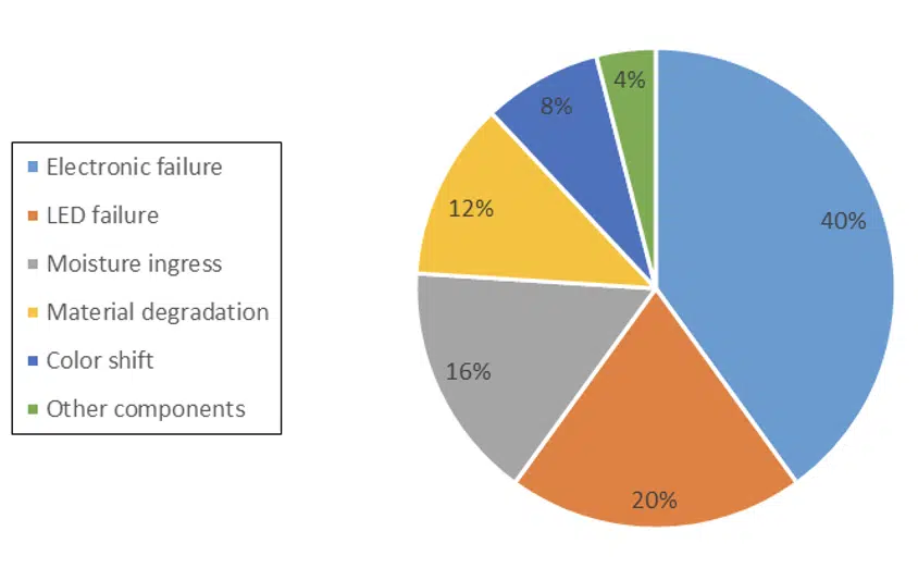
In Figure 1, a pie chart of the root causes of the failures of lighting systems is depicted. It originates from a generic study in the LED lighting world [1]. This chart, with data from up to 2014, shows that electronic failures can be responsible for up to 40% of the total field returns of LED systems. This illustrates the critical need for user-friendly tools to estimate the field returns of LED drivers. More refined modelling capabilities will help to further bring down this contribution.
Figure 1. pie chart of the most common electronics failures in LED systems [1]
Trends and Challenges in LED Driver Life Modeling
There are some market trends, many of them the result of technology push, that shed a new light on the current quality and reliability approaches in the lighting industry.
First, there is a tendency towards miniaturization. In order to enhance the design-in degrees of freedom of drivers, the LED driver size becomes a unique selling point. Although from an architectural point of view, LED drivers do not feature extreme high complexity, they must deal with a myriad of field mission profiles as well as potential issues in public electricity grids that can lead to voltage dips and surges. Temperature constraints need to be addressed up-front in the development process, preferably using prototyping tools, which will be shown hereafter.
With the advent of connected lighting, the use of sensors and wireless technology became widespread. As such, LED drivers include more features, such as passive infrared sensors (PIR) and microwave sensors, that may be used for presence detection. In outdoor applications, light poles communicate with servers that store information (electrical signals, temperature, application mission profiles, etc.). The resulting data sets are highly suited for prognostics purposes.
To guarantee flawless operation during the projected service life, LED drivers are predominantly tested in well-equipped labs with state-of-the-art test facilities. Development teams follow detailed test validation plans to reduce product risks over the project execution. The most commonly executed tests are thermal cycle and shock tests, relative humidity tests, salt mist tests, surge tests, damp heat tests, vibration and mechanical shock tests. The challenge is to integrate knowledge from previous tests into a dedicated modelling tool. In a circular economy, where customer service prevails, the power to predict remaining system life becomes an important asset. Therefore, data analysts and reliability engineers are joining forces to bring prognostics to a higher level. This cannot be done without validation from physics of failure models.
Speaking the Language of rReliability: Modelling the Bath-tub Curve
The bathtub curve is a practical vehicle to illustrate the quality and reliability along the life cycle of LED drivers. Infant mortalities are not accounted for in the presented model. That is because MEOST (multiple environment overstress tests) [2] and the application of FMEA’s or burn-in are successfully used to avoid this first stage of decreasing failure rate.
The well-known parts count method in reliability [3,6] is employed to construct the flat part, using the base FITs (failure in time, in which the time is a billion hours of operation) of the components of the board assembly. For calculation purposes, the latter are corrected for local temperatures, using Arrhenius approaches. For electrolytic capacitors (ELCAPs), ripple currents and local temperatures are accounted for since the latter determine the failure rate.
The third part of the bathtub curve pertains to the wear out. We know from history that solder joint cracking and degradation of electrolytic capacitors are the most important wear out failures for LED drivers. Dedicated physical and empirical models are (being) built and maintained to be integrated in our prototyping tools.
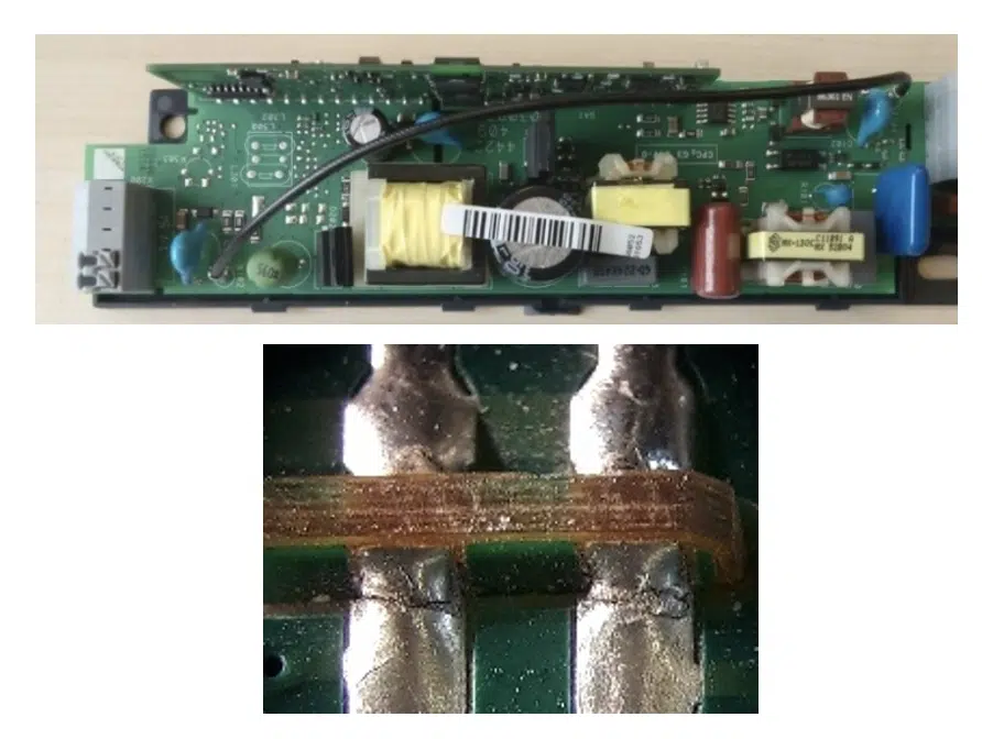
Figure 2. board to board solder joint connects for mother-daughter board PBA configurations (top), cracked board-to-board connections (bottom)
Unless proven otherwise, a LED driver is generally perceived as the weakest link in the system. For random failures, the modelling is rather straightforward, and the parts count method is applied. Various FIT and design analysis calculators are commercially available [3-5]. However, it is often unclear to users which approach to select amongst the possible standards, … some being more conservative than others. Some companies derive product warranties only from their own data. In the example hereafter, a repository of historical data inherited from validation tests originating from Philips/Signify is used. The correction formulae for temperature and deratings are like the ones advocated in the IEC 61709 guideline [6].
For wear out, the focus is chiefly on ELCAP degradation and solder joint fatigue, because these failures are dominant in validation tests under stressed conditions (and are also reported as field returns). Because of practical considerations, the scope is confined to the most critical solder joints. From experience, it is known that two types of solder joints are the most vulnerable to fatigue cracking [7-8].
- Through-hole components like large transformers, can be quite susceptible to solder fatigue cracking, especially when they have large dimensions, combined with relatively large thermal expansion coefficient (CTE) mismatches with the printed boards.
- Board-to-board connections are also critical, in cases when there is a strong mismatch in CTE and the insertion length of the daughter in the mother board is relatively large, as illustrated in Figure 2. Stresses are imposed not only during the application of thermal/power cycles, but also during the thermal excursions used in wave solder. The latter stresses are generally retained as residual stresses within the assembly when it cools down to room temperature. This especially occurs when dealing with lead-free solders, due to the higher reflow temperatures.
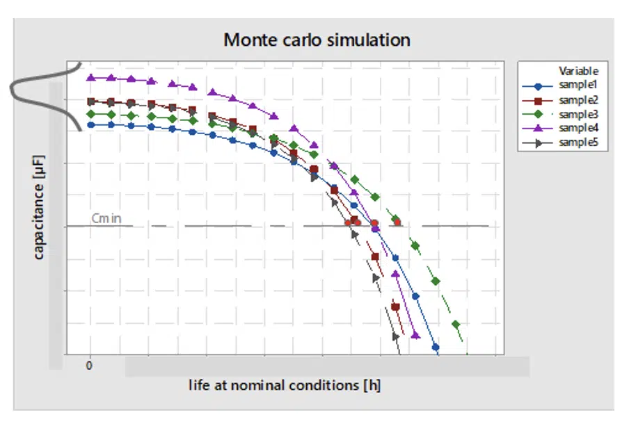
Figure 3. typical shape of the degradation curves of electrolytic capacitors (ELCAPs), due to operational temperature. Cmin is the minimum threshold capacitance, imposed by the application
A second potential source for wear out failures is the electrolytic capacitors [13-14]. Aluminum electrolytic capacitors are fabricated by interleaving paper between two strips of aluminum foil. Foil and paper are wound into an element and impregnated with electrolyte. Such ELCAPs can degrade over time due to ageing of the dielectric, foil degradation, oxide film degradation, and the dry out of the electrolyte [13-14].
Degradation of electrolytic capacitors is modeled in our analysis by means of a stochastic method. Variance is assumed on the initial capacitance value and on the shape of the degradation curve. Figure 3 displays a set of degradation curves that results from Monte Carlo simulations. Companies partnering with ELCAP suppliers have access to their validation tests and hence know the typical shapes of the degradation curves. In the example in Figure 3, the shapes are approximated as the envelope of multiple linear decreasing parts or stages.
When all former elements are available, it is possible to construct the overall reliability curve as the convolution of the following reliability functions [9-12]:
In Equation 1, ‘W.O.” denotes the wear out and “rand” points to random failures. L is the number of components populated on the printed board, M the number of electrolytic capacitors and N the number of critical solder joints. Rather than working with the bath-tub curve, the tool depicts the cumulative probability curve for failure as a function of time, F(t)=1-R(t). Failure points are determined on this function F(t) via Newton Raphson root finding.
For the solder reliability functions in the third part of Eq 1, designed experiments (DoE), in which the laminate choice of the mother board (or CTE mismatch with the daughter card) was varied, were conducted. Other factors in the DoE were the daughter card length and the solder paste. Fatigue experiments were set up with 2 settings of the thermal cycle temperature range (∆T), with well-defined dwell times and ramp times. From this testing, empirical design rules were generated for the cumulative failure probability and are used in the computation for broad level solder joint reliability, shown in Eq 2.
With α(∆T) a design rule for the 63% failure point as a function of the DoE parameters, determined via a maximum likelihood (MLE) fit of the failure data.
Integration into a Calculator
The various building blocks described in paragraphs 2-3 were integrated into a calculator developed for use by validation and quality engineers as well as system architects.
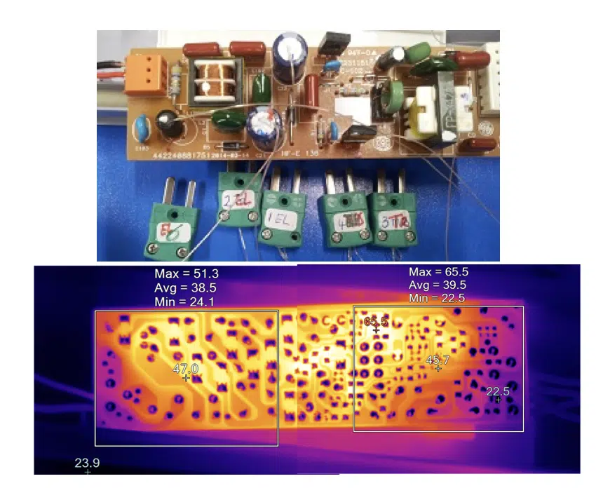
Figure 4. on bread boards (top) or released printed board assemblies (bottom), local hot spots are determined. This info serves for the calculation of the system mean time to failure (MTTF) and the Bx failure points
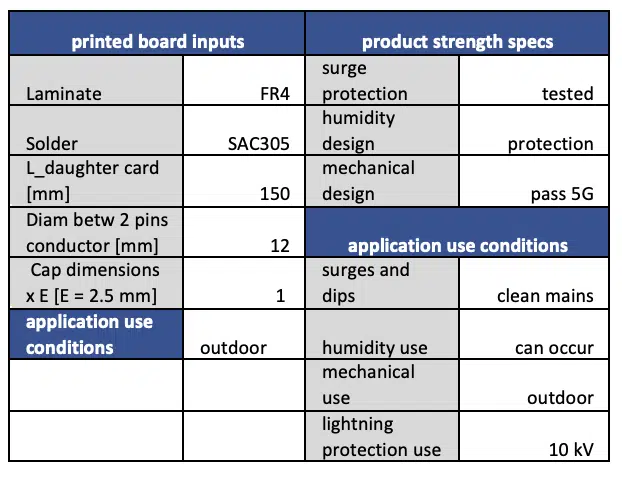
The input to the calculator listed in Table 1 mainly consists of printed board information, solder materials, ELCAP families, design and use-conditions. In the current example, a typical outdoor mission profile is chosen. The design characteristics are traded-off versus the application conditions. In case the design is over-specified, FIT de-ratings are applied using correction factors as proposed in [6], or vice versa. Component dimensions are needed to calculate solder joint life by accounting for shear deformation and creep relaxation. The printed board laminate must be specified to determine mismatches in thermal expansion with the components. Temperature inputs are based on measurements at breadboards for typical use conditions (i.e. the mission profiles encountered in the field). To this purpose, infrared or thermocouple measurements are conducted to identify hot spots, as illustrated in Figure 4. Alternatively, it can be based on Tcase temperatures measured at final driver topologies at full operation, in the dimmed state and after self-heating in the luminaire. By means of the Miner’s rule for accumulated loadings [11-12], this temperature information is used to compute the equivalent failures in time.
A bill of material file, which contains the so-called TVI (Temperature, Voltage derating and Iripple) information, serves as additional input. For each component, information is gathered about the local temperature, the power and voltage derating and for the ELCAPs ripple current deratings.
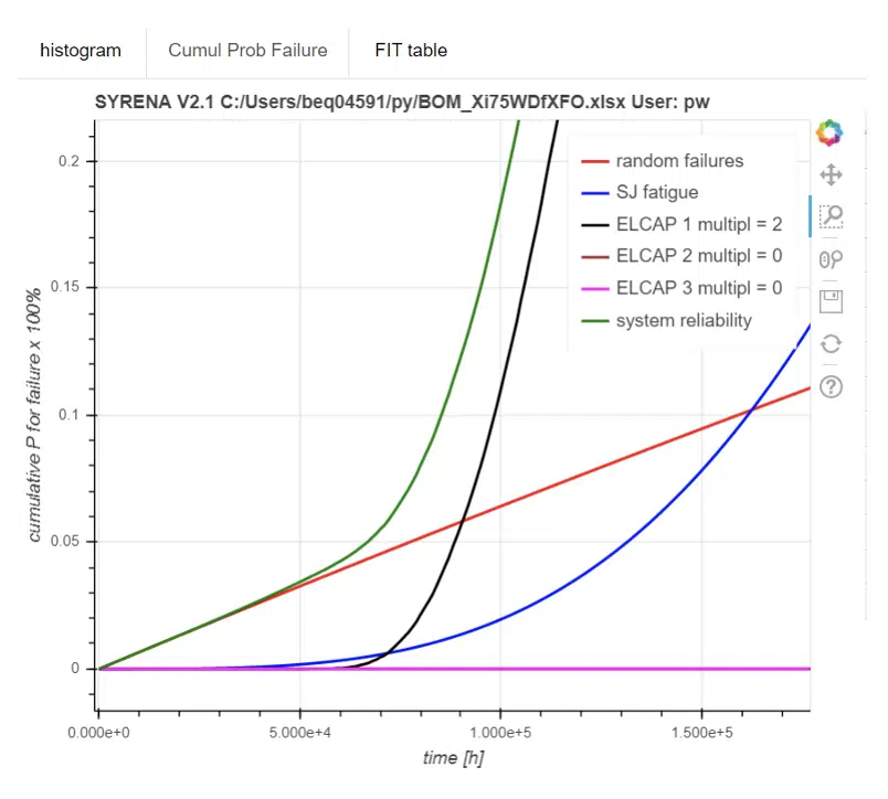
An example of a calculation is given in Figure 5. The green curve labels the cumulative failure probability of the driver system. The black curve does the same for the ELCAP in the driver’s bill of material. The blue and the red curve refer to the failure probability of the solder interconnects and the components respectively. Figure 5 shows that for the computed example wear out of the electrolytic capacitor is more critical than the solder joints, what is reflected in the shape of the system failure curve. The left tail is important for the determination of the 5 and 10 percent failure points of the driver.
Table 1. input example for the ERT calculation
The graphical output in Figure 5 allows information from a prototyping phase to be used to estimate the projected lifetime of a LED driver. A table with the corrected FIT numbers for each component can also be retrieved. In case of outliers in those numbers, it is easy to pinpoint the suspected components for doing design iterations. Once the design has been finalized, the tool can be used to establish product warranties. This framework is indispensable when aiming to build digital twins to assess the rest life of products in the field. In the future, this calculation tool will be made adaptable for such analyses.
Figure 5. cumulative probability for failure as a function of lifetime for an uploaded bill of material
Conclusions and Outlook
Reliability is an important driver to win in LED service contracts. As product maturity increases, customers and original equipment manufacturers (OEM’s) are entitled to ask the rationale behind the derivation of specifications. Leading companies with a design for reliability mindset can easily provide such requested transparency.
It remains worthwhile devoting resources to experimental validation testing and modeling of new LED and driver platforms. These can provide the basis for calculators backed up by powerful physics of failure (PoF) models and a FIT repository.
Product life prediction using log data from built-in sensors or canary devices becomes the new reliability paradigm. This information will be used to train deep learning models, hybrid reliability models and digital twins. The use of big data analytics on the available data sets has the potential pitfall to become an unguided projectile, if not supported by any PoF model. Accordingly, work remains to be done to crystallize all the good initiatives. Having a permanent focus that continuously refines reliability models and updates correction formulae is key to successfully improve reliability prediction.
References
[1] Next Generation Lighting Industry Alliance LED Systems Reliability Consortium, LED luminaire lifetime: recommendations for testing and reporting, 3rd edition, 2014.
[2] K. Bhote and A. Bhote, “World Class Reliability using multiple environment overstress testing (MEOST) to make it happen”, AMACOM, (2004)
[3] FIDES guide 2009 Edition A, September 2010 Reliability Methodology for Electronic Systems
[4] https://www.dfrsolutions.com/what-is-sherlock-ansys
[5]https://www.ptc.com/en/products/plm/plm-products/windchill
[6] IEC 61709, “Electric components – Reliability – Reference conditions for failure rates and stress models for conversion”, Ed 3.0, (2017)
[7] J.P. Clech, “ACCELERATION FACTORS AND THERMAL CYCLING TEST EFFICIENCY FOR LEAD-FREE SN-AG-CU ASSEMBLIES”, presented at SMTAI Chicago, IL, (2005)
[8] W. Engelmaier, “Solder Joint Reliability – Theory and Applications”, ed. J.H. Lau, Van Nostrand Reinhold, New York, (1991), 545
[9] M. Rausand and A. Hoyland, “System Reliability theory”, Wiley, (2003)
[10] W. Van Driel and X.J. Fan, “Solid state lighting reliability: components to systems”, Springer, (2013)
[11] P. O’Connor, “Practical Reliability Engineering”,Wiley (2002)
[12] D. Crowe and A. Feinberg, “Design for reliability”, CRC Press, (2001)
[13] S. Gulbranson, “Accelerated aluminum electrolytic capacitor life testing”, DfR Solutions, not published
[14] T. Ashburn, D. Skamser, SMTA Medical Electronics Symposium – Anaheim, California – 2008
Acknowledgments
Prof. W.D. Van Driel, X.J. Zhao, H. De Vries, G. Van Hees, U. Boeke and R. Engelen are gratefully acknowledged for the stimulating discussions and the sharing of data for this article.
