Written by: Sevket U. Yuruker, Raphael K. Mandel, Amir Shooshtari and Michael M. Ohadi – Department of Mechanical Engineering, University of Maryland
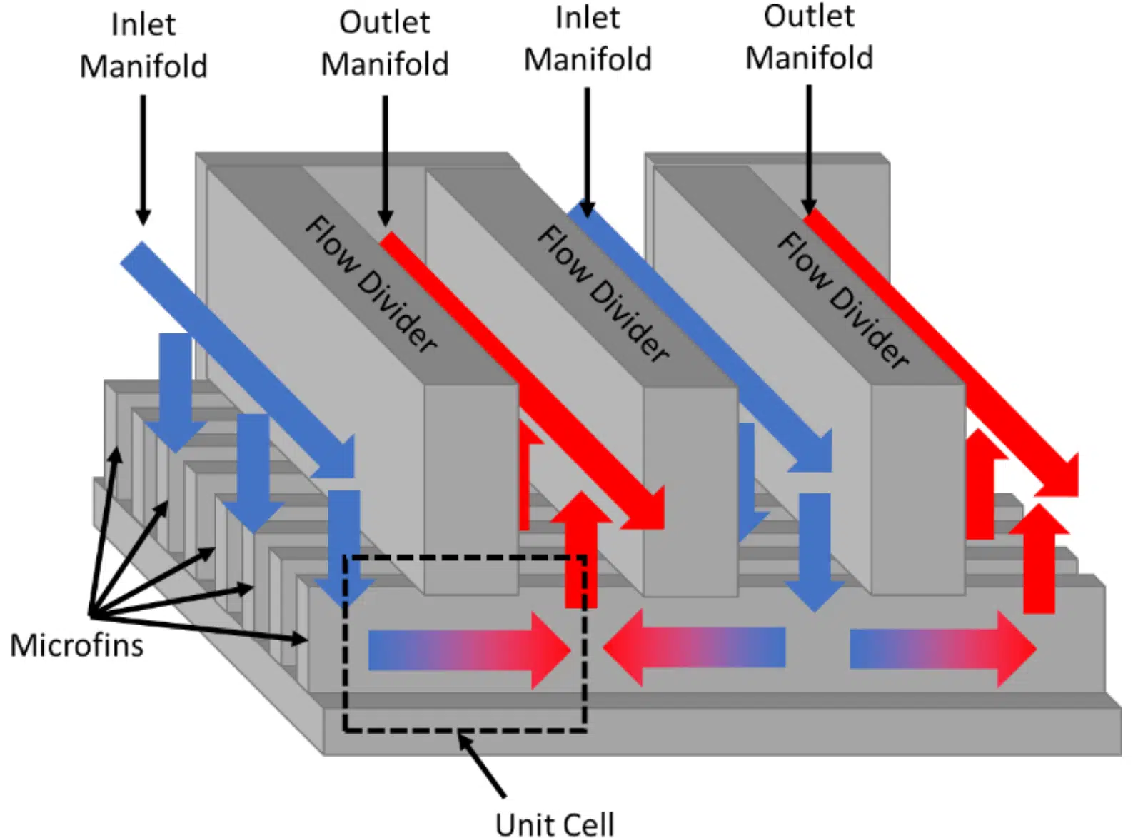
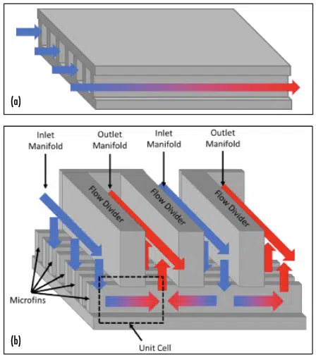
Conventional microchannel cooling has been proven capable of removing high heat fluxes, but usually at significant pressure drops. On the other hand, manifold microchannel systems offer high heat transfer coefficients/heat removal rates, but at significantly reduced pressure drops compared to traditional microchannel cooling [1–5]. Manifold-microchannels (MMC) can achieve reduced pressure drops at increased heat transfer rates by dividing long microgrooves into an array of parallel microchannels using manifolds, as shown in Figure 1. However, the optimal design of a manifold microchannel system depends on the particular application and its operating conditions.
Since currently validated correlations do not exist for manifold microchannels, optimization is usually performed using CFD, which is computationally demanding and time-consuming. Instead, the pressure drop and heat transfer of a given manifold-microchannel design, for specific fluid and operating conditions, often can be easily calculated if the two most relevant dimensionless parameters, Nusselt and Poiseuille numbers, are known a priori. This would reduce the engineering efforts and computational cost to design effective MMC systems to be utilized in a variety of electronic cooling applications with ultra-high heat fluxes, such as power electronics systems, high power laser systems, electric motor cooling and data center thermal management.
In this study, a wide range of dimensionless parameters that define the manifold microchannel design and its operating conditions were simulated using a commercial CFD software package to obtain pressure drop and heat transfer coefficients. Their corresponding dimensionless performance parameters, namely the Nusselt and Poiseuille numbers, are then curve fitted into a correlation, details of which, including an optimization case study at the end, have been previously published by Yuruker et al. [6]. Finally, a step-by-step procedure of how the correlation can be utilized in predicting the performance of a real heatsink design is provided with an example case.
Analysis
Figure 1: a) Traditional/straight microchannel system b) Manifold microchannel system.
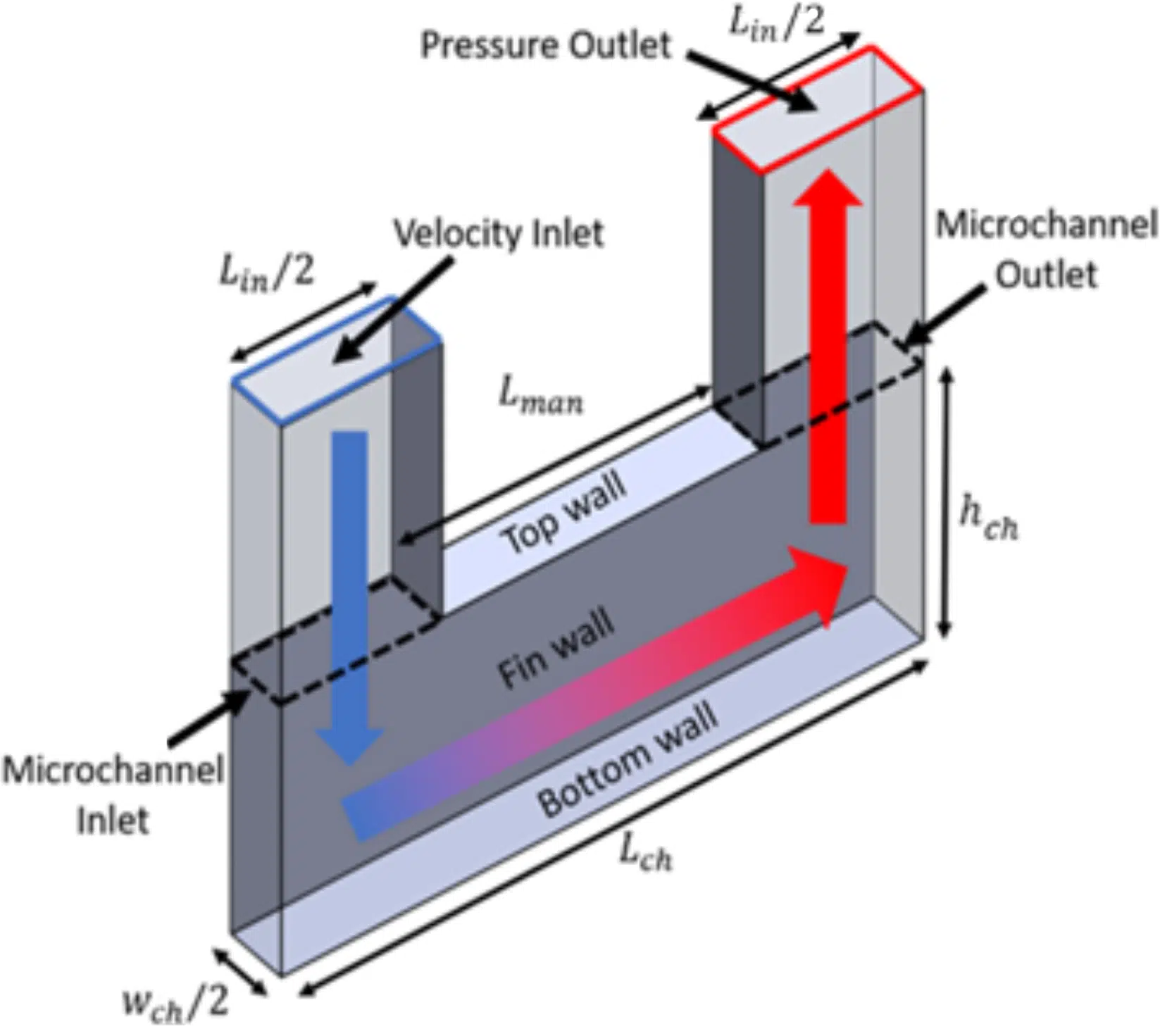
Due to the periodic nature of manifold-microchannels, the computational domain chosen for this study is a unit cell portion of the complete manifold microchannel system, shown by dotted lines in Figure 1. The unit cell with relevant dimensions and boundary conditions is shown in Figure 2. Symmetry boundary conditions are imposed on the transparent sides of the channel while a wall boundary condition is applied on the remaining sides. A constant temperature is maintained on the bottom wall and fin wall, while the top wall is adiabatic due to the assumption that the manifold is pressed onto the manifold and that the manifold is not a thermally conductive material (such as plastics); for cases where the manifold is metal (or thermally conductive) and is in good thermal contact with microchannels, a separate set of simulations would need to be performed. Constant velocity and temperature conditions are applied at the inlet, and zero pressure is applied to the pressure outlet. For simplicity, the inlet and outlet lengths are always equal in this study and the definitions of the geometric variables are shown in Figure 2.
The assumptions and simplifications used in the CFD model are listed as follows:
(1) Steady-state, laminar and incompressible flow
(2) Effect of gravity is negligible
(3) Constant fluid properties
(4) Constant wall temperature
(5) Contraction/expansion at the manifold-microchannel interface have negligible effect on heat transfer and pressure drop inside the microchannel.
Figure 2: Unit cell manifold microchannel model.
The total pressure drop across the MMC system will include contribution from the manifold section as well, but as mentioned above this is not in the scope of this work. For this, external calculations or CFD will be required. One suggestion is utilization of a hybrid method introduced by Arie et.al., which assumes a 1D flow in the manifold, enabling reduction of the governing equations into a single differential equation as a function of velocity in the manifold [9,10]. Another suggestion is building a system level CFD model of the MMC architecture, yet representing the microchannel array as a unified porous media domain [11]. The velocity vs. pressure drop and heat transfer characterization of the microchannel can be priorly done using the correlation given in this study, and applied to the porous media settings. This method significantly reduces the mesh complexity and computational power requirement as small microchannels do not need to be modeled individually.
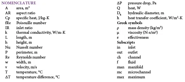
A useful correlation should be applicable to a wide range of geometries and operational conditions. To make this possible, the manifold-microchannel geometry is defined in terms of three dimensionless parameters: aspect ratio (AR), inlet ratio (IR), and velocity ratio (VR), which are defined in Eqs. (1)-(3):
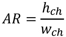
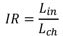
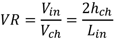
where wch, hf, Lin, and Lch are defined in Figure 2.
The Reynolds number in the microchannel is the first operational dimensionless parameter to be determined and is defined as
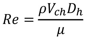
where Dh is the hydraulic diameter and is defined as

The second operational dimensionless parameter considered is the Prandtl number, which is the main input related to fluid selection in the numerical analysis:
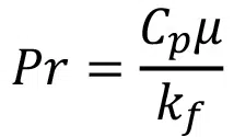
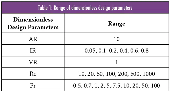
Once these five parameters are specified –AR, IR, VR, Re, and Pr – the microchannel geometry and operational conditions for the CFD simulation can be computed from Equations 1-7.
Since the main points of interest are the pressure drop and heat transfer within the microchannel itself, the contribution from the manifold portion of the model is excluded by measuring pressures and temperatures at the microchannel inlet and microchannel outlet surfaces, as shown in Figure 2. The pressure drop is non-dimensionalized as the Poiseuille number, fRe, and is defined as
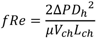
with

where P, and are the area-averaged pressures computed directly by the CFD software on the microchannel inlet and outlet faces, respectively (see Figure 2):
Similarly, the Nusselt number, Nu, is used as the dimensionless performance metric for heat transfer. The Nusselt number is calculated as

where hwall is the heat transfer coefficient at the walls and kf is the thermal conductivity of the fluid. The heat transfer coefficient can be calculated from the number of transfer units, NTU, and

For a constant temperature condition, NTU is related to the heat exchanger effectiveness, ɛ, as

and ɛ is the ratio of actual heat transfer at the walls to the maximum possible heat transfer:

where Tin and Tout are the mass-averaged fluid temperatures at the microchannel inlet and outlet, respectively and are computed directly with CFD. Using Equations 8-13, the two dimensionless performance metrics fRe and Nu are calculated from the dimensional results obtained by CFD.
To accurately capture the boundary layer near the walls with the least computational expense, mesh inflation was used on all walls and in all three dimensions. To ensure that the simulations were mesh-independent, each simulation was performed with a series of mesh levels with the number of cells ranging roughly from 40,000 to 160,000. Only cases with less than 1% difference between the two finest mesh levels were considered mesh-independent and the rest were discarded. The simulations are solved with a first-order upwind scheme using the coupled algorithm in the CFD software. The convergence criteria for the momentum/continuity and energy are set to 1×10⁻⁵ and 1×10-12, respectively.
Results
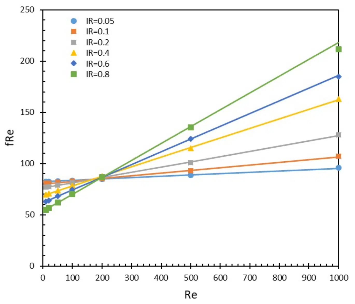
Figure 3: Poiseuille number as a function of Reynolds number. Symbols represent the CFD data and lines represent the curve fitted data.
The 490 simulations were performed, as described, and the resultant performance metrics – Poiseuille and Nusselt numbers – were found to be functions of the three dimensionless parameters, IR, Re, and Pr. A linear relationship between Poiseuille number and Reynolds number was observed for all IR values, as shown in Figure 3. Thus, it can be concluded that fRe has the form

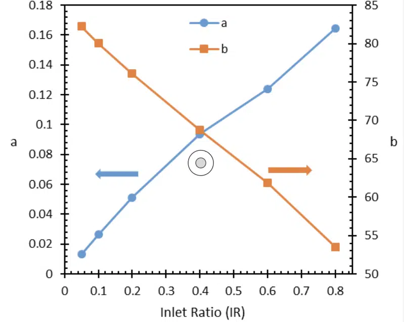
where a and b coefficients solely depend on the geometric parameters AR, IR, and VR. The constant term b represents the contribution from fully developed flow, and is independent of Re, as expected. However, the channel has a developing region, as well as two turns at the inlet corner and outlet corner, which contribute to fRe and their magnitude scales with Re. Thus, the first term in Equation 14 a x Re, corresponds to the contribution from turning and developing flow losses. At smaller IR, developing and turning losses are smaller, as the channel is very long and the majority of the pressure drop occurs in the straight section of the channel. For high IR, the straight section is short and the majority of the losses are due to turning and developing flow and the flow may never fully develop. For lower Reynolds, the developing and turning loss contributions are small (as they directly scale with Re) and thus it can be seen that low IR cases (with longer straight channel sections) have larger fRe. Similarly, for larger Reynolds numbers, the turning and developing losses dominate; therefore those cases with larger IR (with shorter straight sections, almost like a U-shape) have larger fRe. Interestingly at Re=200, there seems to be a balance between the turning/developing/ developed flow contributions to fRe, and it collapses to a single point. Thus, for the chosen AR and VR, at Re=200 the fRe is not a function of IR. It must be noted that the Reynolds at which this happens is a function of AR and VR and will not always occur at 200 for other values of AR and VR. Since only IR was varied in the present work, only the variation of a and b as a function of IR is discussed. The variation of a and b with IR is shown in Figure 4.
Figure 4: Curve fitted coefficients of fRe.
The results indicate that the multiplier coefficient a increases with Re while b decreases. a and b seem to have a very linear behavior and can be fitted linearly with IR for ease of use for the readers, however it must be noted that for IR>0.8 or for other values of AR or VR, the coefficients may not always behave linearly, and thus a linear fit may be a large source of error.
As IR approaches 0, the geometry approaches that of a straight microchannel. According to the literature, for a fully developed rectangular duct with AR=10, fRe is ~84 [7]. Thus, a noteworthy observation is that the curve fitted coefficient b also approaches this value as IR → 0, which can be visually seen in Figure 4.
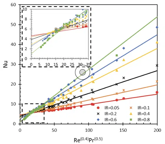
Figure 5: Nusselt number as a function of Re(0.4)Pr(0.5). Markers represent the CFD data and lines represent the curve fitted data.
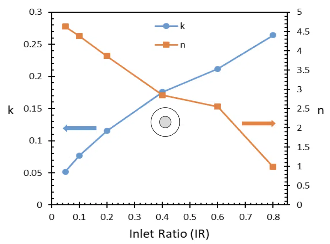
Similarly, it was observed from the data shown in Figure 5 that the Nusselt number has a linear relationship with Re0.4Pr0.5. The form of the Nusselt number is similar to the form of the well-known Dittus-Boelter and Sieder-Tate equations [8]. However, in both Dittus-Boelter and Sieder-Tate correlations, the condition where Re approaches zero is not well accounted for, since the correlation is only valid for turbulent flows. For laminar flows, it is known that even if Re=0, fully developed heat transfer will occur and thus, the Nusselt number will be nonzero. Thus, an additional term ‘n’ is added to the Dittus-Boelter equation to establish an expression that is valid in the laminar flow regime:

The variations of k and n with IR are shown in Figure 6.
Figure 6: Curve fitted coefficients of Nu.
When the correlation was tested against the data points used in its creation, a mean error (deviation) of 0.4% and maximum error of 0.7% for fRe were observed, respectively. For Nu, the mean error was again 0.4%, while the maximum error was within 11.2%, which is reasonably accurate.
A Step-by-Step Guide for using the Correlation
An example heatsink design and its thermo-fluidic performance evaluation are given below to serve as a guide in using the correlation. A MMC heatsink with a channel width of 0.1mm, channel height of 1mm, channel length of 5mm, and the inlet length of 2mm is considered. In this design, there will be 4 channels in the direction of the channel length and 20 channels in the direction of its width, resulting in a total of 80 microchannel segments, such as that shown in Figure 2. When Equations 1-3 are evaluated for the unit cell geometry, the dimensionless variables are AR=10, VR=1, and IR=0.4. If the working fluid is water at room temperature (Pr=7, µ=0.01 Pa-s, ρ=1000kg/m3, kf=0.6 W/mK), and if the total volumetric flow rate into the MMC heatsink is 1.1e-5 m3/s, each channel gets 1/80th of this flow rate, i.e., 1.38e-7 m3/s. For this flow rate, the Reynolds number inside a channel can readily be calculated using Equations 5-6 to be Re=250.
To predict the pressure drop for the given geometry and operating conditions, Eq.13 has to be evaluated. The terms “a” and “b” for IR=0.4 can be found in Figure 4 to be 0.09 and 69 respectively. Then, using Equation 13 at Re=250 we calculate fRe=91.5. Now using Equation 8, pressure drop () can be readily calculated to be 104 Pa.
Similarly, to predict the heat transfer coefficient for this design, Equation 15 must be evaluated at the given Re=250 and Pr=7.5 conditions. The coefficients “k” and “n” for IR=0.4 can be found from Figure 6, and are 0.17 and 2.9, respectively. Now using Eq 15, we find Nu=7.14. Using Equation 10, hwall can be readily calculated to be 23,555 W/m2K. If an effective base heat transfer coefficient for the entire heatsink is desired to be calculated, the fin efficiency equation, which is commonly found in any heat transfer book, can be utilized for the selected solid material conductivity and fin thickness [6]
This entire process can be programmed into commercially available coding software and any particular design at any operational conditions (flow rate and fluid selection) can be evaluated nearly instantly. This enables many design iterations to be evaluated in a significantly reduced time as opposed to CFD analyses. Therefore, it is a powerful tool when a design optimization is to be performed. Detailed examples of such an optimization process, with corresponding CFD validations, can be found in [6]
Conclusions
This work presented a convenient method for researchers and engineers to evaluate heat transfer and pressure drop performance of manifold microchannel heat sinks using a closed-form correlation. The correlation circumvents the need for computationally intensive CFD analysis and provides reasonably accurate results with maximum errors within 1% for pressure drop, and 12% for heat transfer predictions. The computational time required for optimizing the design of a manifold microchannel system is reduced from weeks to seconds. This enables and encourages MMC systems to be adopted and utilized in high heat dissipating electronic systems, such as high-power laser systems, power converter/inverter systems, electric motors applications as well as data center thermal management.
For future work, the range of the correlation should be widened to cover all possible geometrical parameters AR, IR, and VR, thus allowing diverse microchannel designs across different application areas to be evaluated.
References
[1] G. M. Harpole and J. E. Eninger, “Micro-channel heat exchanger optimization,” in Proceedings – IEEE Semiconductor Thermal and Temperature Measurement Symposium, Feb. 1991, pp. 59–63, doi: 10.1109/stherm.1991.152913.
[2] D. Copeland, M. Behnia, and W. Nakayama, “Manifold microchannel heat sinks: Isothermal analysis,” IEEE Trans. Components Packag. Manuf. Technol. Part A, vol. 20, no. 2, pp. 96–102, Jun. 1997, doi: 10.1109/95.588554.
[3] E. Cetegen, “FORCE FED MICROCHANNEL HIGH HEAT FLUX COOLING UTILIZING MICROGROOVED SURFACES,” University of Maryland, College Park, 2010.
[4] R. Mandel, A. Shooshtari, and M. Ohadi, “A ‘2.5-D’ modeling approach for single-phase flow and heat transfer in manifold microchannels,” Int. J. Heat Mass Transf., vol. 126, pp. 317–330, Nov. 2018, doi: 10.1016/j.ijheatmasstransfer.2018.04.145.
[5] S. U. Yuruker, R. K. Mandel, P. McCluskey, and M. Ohadi, “A Vertically-Enhanced Manifold Microchannel System (VEMMS) for Thermal Management of Power Electronics,” IEEE Trans. Components, Packag. Manuf. Technol., pp. 1–1, 2021, doi: 10.1109/TCPMT.2021.3082771.
[6] S. U. Yuruker, R. K. Mandel, A. Shooshtari, and M. M. Ohadi, “A metamodeling approach for optimization of manifold microchannel systems for high heat flux cooling applications,” in InterSociety Conference on Thermal and Thermomechanical Phenomena in Electronic Systems, ITHERM, 2019, vol. 2019-May, doi: 10.1109/ITHERM.2019.8757232.
[7] S. I. Edition, Y. a Çengel, and J. M. Cimbala, “Fluid Mechanics : Fundamentals and Applications,” pp. 1–117, 2010, doi: 10.1016/B978-0-12-405935-1.18001-3.
[8] Y. A. Çengel and A. J. (Afshin J. Ghajar, Heat and mass transfer : fundamentals & applications. .
[9] Arie, M. A., Shooshtari, A. H., Dessiatoun, S. V., Al-Hajri, E., & Ohadi, M. M. (2015). Numerical modeling and thermal optimization of a single-phase flow manifold-microchannel plate heat exchanger. International Journal of Heat and Mass Transfer, 81, 478-489.
[10] Arie, M. A., Shooshtari, A. H., Rao, V. V., Dessiatoun, S. V., and Ohadi, M. M. (December 28, 2016). “Air-Side Heat Transfer Enhancement Utilizing Design Optimization and an Additive Manufacturing Technique.” ASME. J. Heat Transfer. March 2017; 139(3): 031901. https://doi.org/10.1115/1.4035068
[11] Battaglia, F, Mandel, R, Shooshtari, A, & Ohadi, MM. “A Porous Medium Approach for Single-Phase Flow and Heat Transfer Modeling in Manifold Microchannel Heat Exchangers.” Proceedings of the ASME 2020 International Technical Conference and Exhibition on Packaging and Integration of Electronic and Photonic Microsystems. Virtual, Online. October 27–29, 2020. V001T05A002. ASME. https://doi.org/10.1115/IPACK2020-2564
