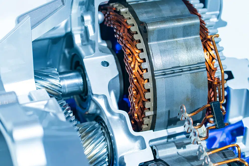
This article reviews integration approaches and, by employing finite element analysis (FEA), compares thermal management solutions for the combined electric motor and power electronics systems for electric vehicles. Integration of power electronics into the electric motor helps achieve higher power densities in the electric traction drive systems. The benefit of integration from the thermal management perspective is the potential for using a single-fluid loop instead of two separate cooling systems for the electric machine and the power electronics/inverter.
Introduction
The number of vehicles on roads with electric propulsion systems is constantly increasing. The global market share of electric and hybrid vehicle sales increased from 2.5% in 2019 to 4.2% in 2020 [1]. According to Deloitte Insights forecasts, by 2030 electric vehicle (EV) market share of new car sales will reach 27% in the United States, 42% in Europe and 48% in China [2].
As demand for EVs is increasing, so is their traction drive power and power density. The push to increase power densities of electric traction drive systems dictates combining the electric motor and power electronics (PE) into one unit to reduce the volume, allowing the unit to be used on multiple vehicle platforms. A single drive unit with fewer interconnecting components also facilitates fast, automated assembly of electric vehicles, driving production costs down and enabling wider adoption of EVs.
Thermal design of today’s powerful electric drives is as important as electromagnetic and mechanical design of the electric machine [3]. Integrating power electronics with the electric motor further complicates the thermal management of the combined traction drive system. Two main heat-generation sources in electric vehicles (apart from batteries), often with different cooling requirements and heat removal strategies, are combined into a common space. However, this integration also provides an opportunity for using a single cooling system instead of two separate cooling loops for the electric motor and the power electronics/inverter.
Cooling the electric traction drive in a vehicle can be accomplished by circulating coolant, such as water-ethylene glycol (WEG) or oil, through the stator case or internal passages in the motor, thereby removing heat from the components. Another effective method for cooling an electric motor is fluid, such as automatic transmission fluid (ATF), impingement directly on components where heat is generated. This technique avoids the conduction path thermal resistance through the passive stack of other materials present in a water jacket WEG cooling scenario [4], thereby reducing thermal resistance and further lowering key component temperatures. The heat is ultimately rejected to the ambient air.
Integration trends
In this article, we review the main trends in the integration of electric vehicle propulsion systems and their thermal management solutions. Using publicly accessible scientific literature, published automotive original equipment manufacturer materials, and interactions with other research groups, we identified three main topologies (Figure 1):
PE enclosure attached to an electric motor case, eliminating the wire harness, but with separate (often sequential) cooling loops [5,6]
PE radially integrated onto the electric motor case with a shared cooling loop [7,8]
PE axially integrated onto the front/back of the electric motor case with potentially a single-fluid cooling solution (circulating WEG or using ATF jet impingement) [9,10].
Figure 1. Integration concepts: (a) separate PE enclosure attached to the motor case, (b) PE distributed/mounted radially on the motor casing, and (c) PE integrated axially in the motor front/back plate.
Each of these approaches is implemented with some degree of variation by different manufacturers or research/design teams. Additional overview and integration enabling technologies are reviewed in Chowdhury et al. [11].
Thermal models and analysis
Based on the identified integration trends, simplified computer-aided design (CAD) and thermal models of the integrated traction drives were created. For the electric machine geometry, the 2016 BMW i3 electric traction motor was used. The selection was based on access to its geometry/materials and availability of its detailed benchmarking/losses data [12,13]. The motor losses were used as thermal loads for the thermal simulations. The power electronics model was based on newer silicon-carbide (SiC) metal–oxide–semiconductor field-effect transistor (MOSFET) dies [14]. These SiC power devices were previously used by Oak Ridge National Laboratory (ORNL) for modeling a simulated control of the BMW i3 motor with a six-phase power module. Thus, their estimated losses/thermal loads were also available [15].
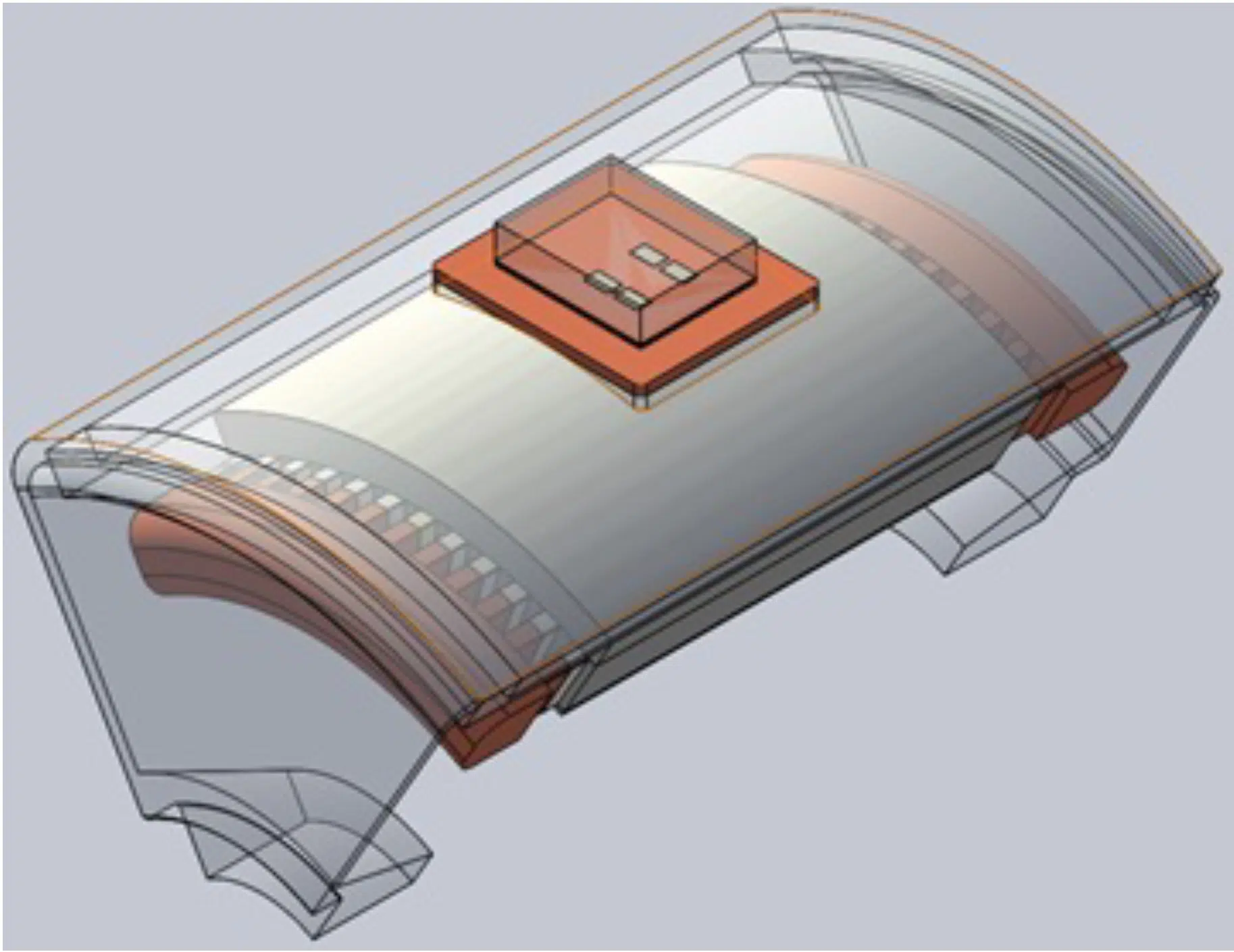
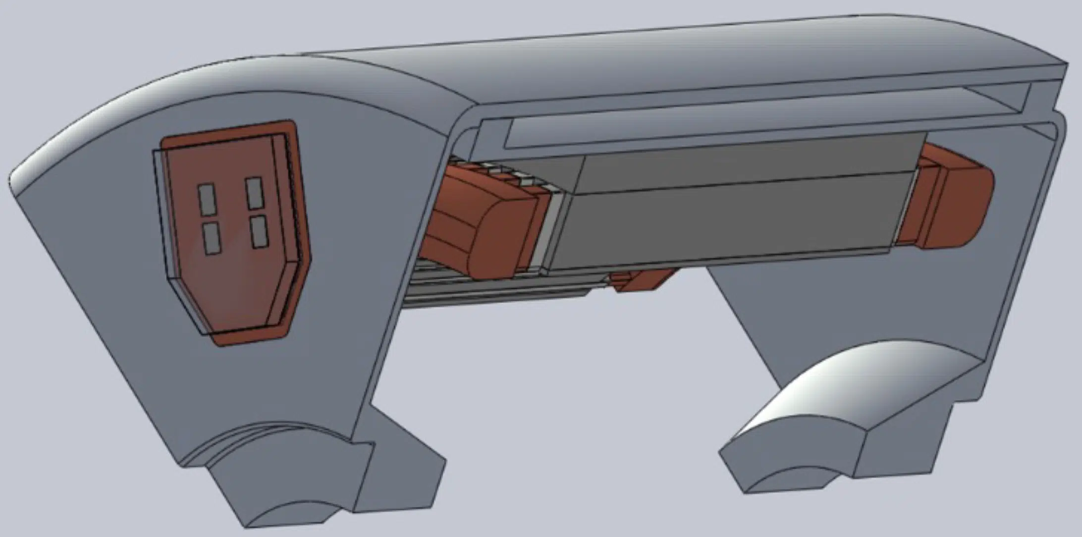
The thermal management strategy for the integration concept shown in Figure 1a, with a separate enclosure for power electronics, would resemble one with a completely independent inverter/power electronics and motor. Therefore, radially (Figure 1b) and axially (Figure 1c) integrated power electronics cooling concepts are of special interest. Hence, respective CAD (see Figure 2 and Figure 3) and thermal models (Figure 4 and Figure 5) were developed and analyzed. For computational efficiency and due to symmetry (PE modules are assumed to be evenly distributed on the outer casing of the motor), only one-sixth of the drive was simulated in the finite element analysis (FEA) simulations.
Figure 2. Radially integrated CAD model based on the BMW i3 traction motor and SiC power devices (shared cooling jacket): one-phase power module with one-sixth of the motor.
Figure 3. Axially integrated CAD model based on the BMW i3 traction motor and SiC power devices: one-phase power module with one-sixth of the motor.
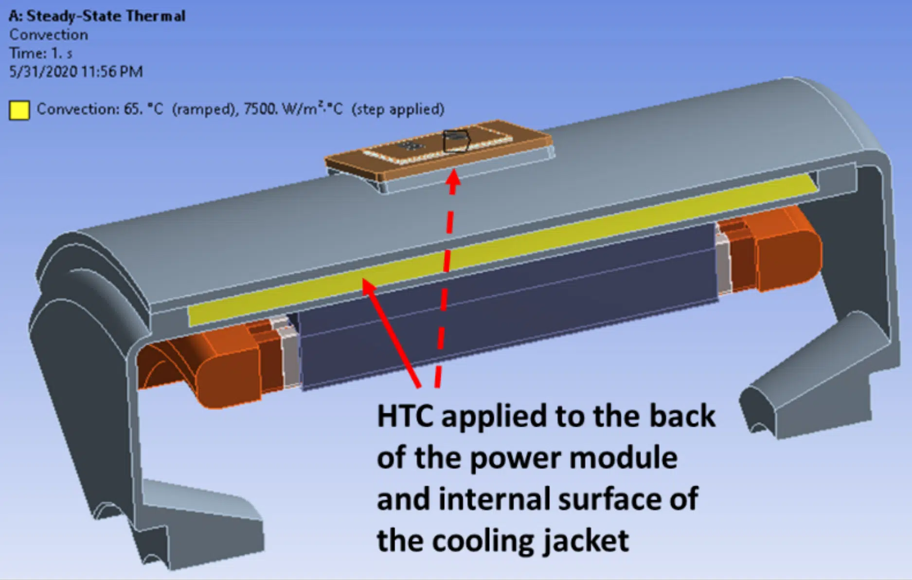
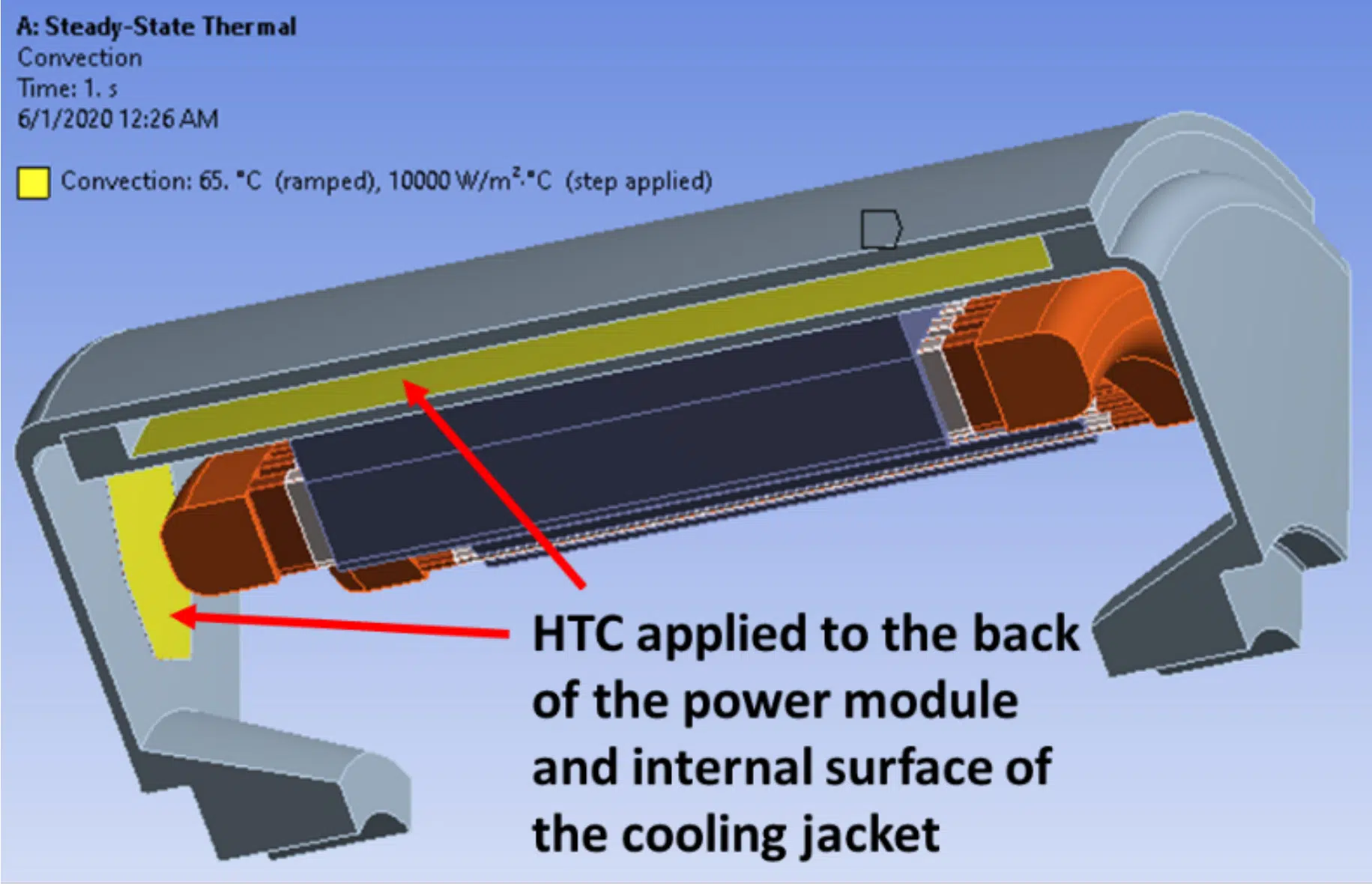
FEA thermal simulations were carried out with commercially available software [16] by applying thermal loads distributed in the motor components as internal heat generation in the windings, stator yoke, shoe, and teeth. For the power module, the heat flow was applied to the top surface of the devices, as most of the heat is generated in a junction area in a thin layer close to the top surface of the power device. Coolant temperature was assumed at Tfluid =65°C and a convective heat transfer coefficient (HTC) was applied to the internal surfaces of the cooling jacket and the back surface of the power module copper base plate (see Figure 4 and Figure 5), which is exposed to the coolant flow or impinging jets through the openings in the case enclosure. The HTC was varied from h = 20–75,000 W/m2K for each configuration. The HTC range spans from the upper end of air natural convection (20–25 W/m2K) to forced air convection (50–500 W/m2K), forced liquid (WEG) convection with jet impingement toward the higher end (500–50,000+ W/m2K), and phase-change (10,000–75,000+ W/m2K) cooling techniques.
Figure 4. HTC applied to the internal surfaces of the cooling jacket and the back of the power module copper base plate—radially integrated configuration shown.
Figure 5. HTC applied to the internal surfaces of the cooling jacket and the back of the power module copper base plate—axially integrated configuration shown.
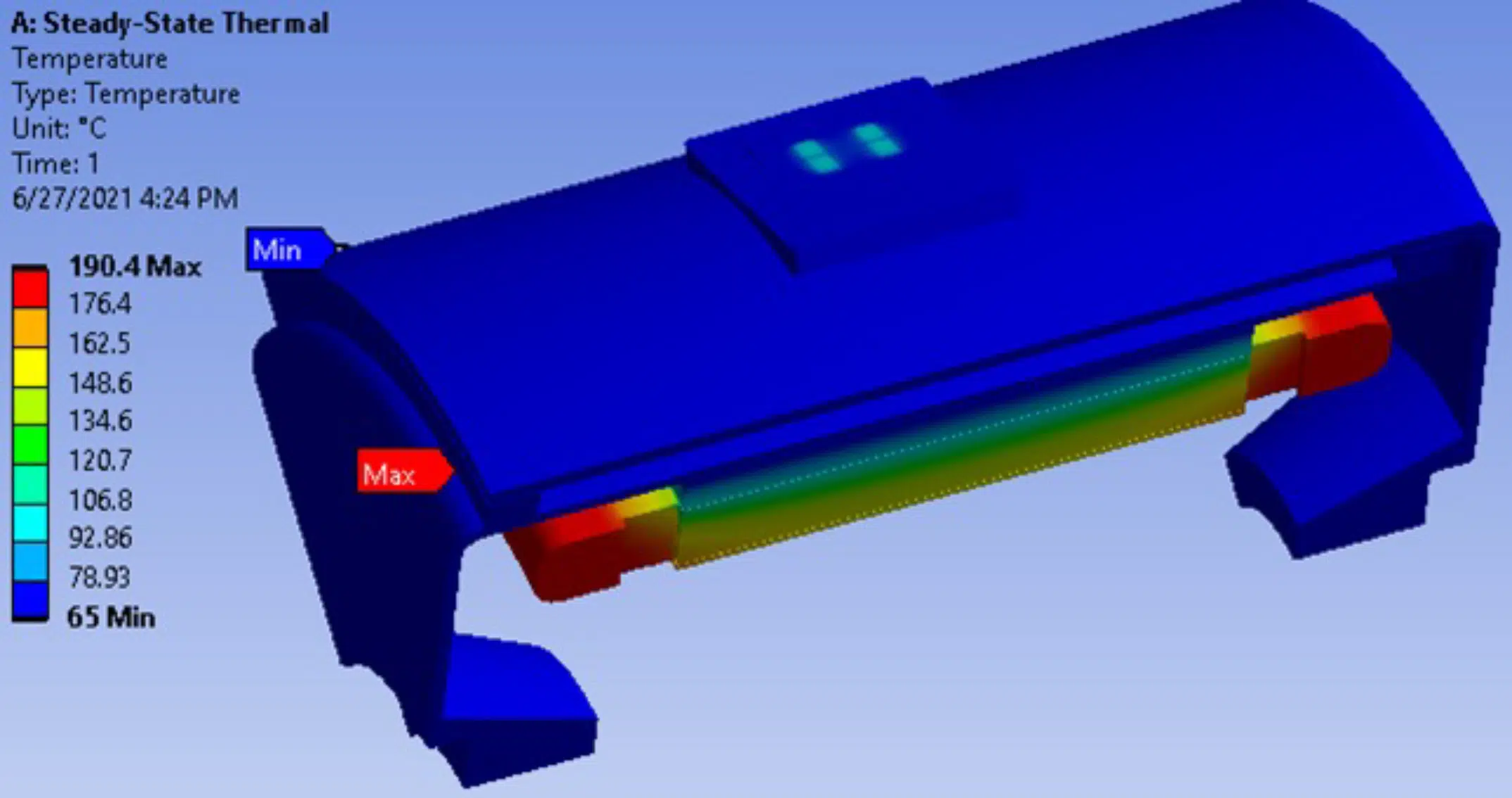
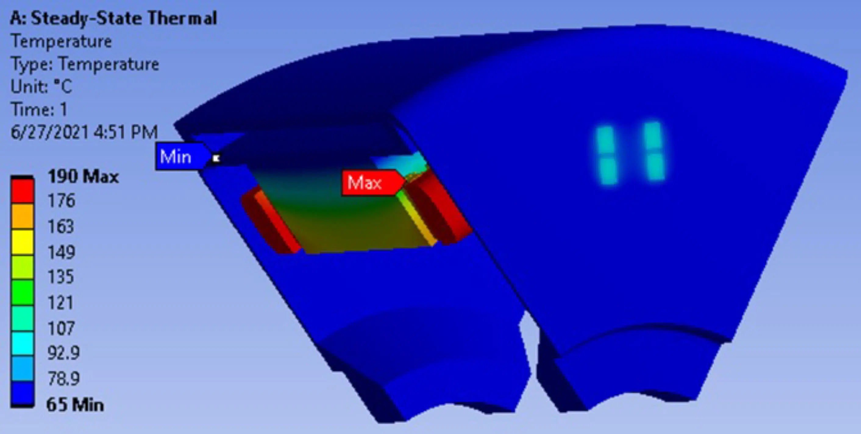
The integrated power electronics cooling approach for both the radial and axial integration configurations seem reasonable, as the SiC power device temperatures were below key motor component temperatures. For illustration, one set of results for each power integration configuration are provided in Figure 6 and Figure 7.
Figure 6. Temperature distribution from the FEA thermal model for the radially integrated power module.
Figure 7. Temperature distribution from the FEA thermal model for the axially integrated power module.
As can be seen from Figure 6 and Figure 7, the highest temperatures (above 150°C) can be observed in the winding end-turns, where a large amount of heat is generated and the thermal path resistance to the cooling fluid is the highest. From a thermal management perspective, the application of ATF or other EV-specific dielectric driveline fluid jet impingement cooling techniques to winding end-turns may benefit overall temperature distributions within the traction drive. Axial integration provides an excellent opportunity for cooling the back side of the power module with ATF or dielectric driveline fluid jets. With a single delivery channel, nozzles could be positioned with jets on one side impinging on the winding end-turns, and jets in the opposite direction cooling the back side of a power module.
In the radial integration configuration, a shared cooling jacket with WEG coolant seems an optimal solution for simultaneous cooling of the power module and electric motor.
Conclusions
Based on the current market and research publications overview, three main integration approaches were identified for electric traction drives. All three integration approaches yield volumetric and weight savings compared to the traditional traction system solutions. In the baseline case (1), simply bringing power electronics closer and attaching its housing to the electric motor eliminates the interconnection harness between the electric motor and power electronics and reduces the number of required parts. However, this minimal integration approach most likely requires either separate parallel cooling loops or single sequential coolant flow in the electric motor and the power electronics enclosures. In the radial integration case (2), the cooling options are limited to a shared cooling jacket with circulating WEG, cooling both the electric motor and the power electronics. For the axial integration case (3), both WEG and ATF/driveline fluid jet impingement cooling options are available. If the WEG cooling option is selected, the coolant channels can be integrated into the front/back of the motor casing, converting it to a cold plate, as well as the traditional radial cooling jacket. In the case of ATF/driveline fluid jet impingement cooling, a single channel can deliver fluid both to winding end-turns and the back of the power electronics.
These integration cases show that, with careful design and selection of the appropriate cooling techniques, sufficient cooling can be achieved both for the electric motor and the power electronics with a single, compact thermal management solution.
Tight integration of power electronics into electric motor enables volume, mass and cost savings on their enclosures, interconnections, their cooling systems, and overall number of required parts. This makes electric vehicle propulsion system lighter and more efficient.
Acknowledgments
The authors would like to acknowledge the support provided by Susan Rogers, Technology Manager of the Electric Drive Technologies Program, U.S. Department of Energy Office of Energy Efficiency and Renewable Energy Vehicle Technologies Office. The authors would like to also acknowledge the support from Kevin Bennion, Emily J. Cousineau, Xuhui Feng, and Gilbert Moreno from the National Renewable Energy Laboratory, as well as from Shajjad Chowdhury and Tsarafidy Raminosoa in ORNL’s Power Electronics and Electric Machinery Group’s research and development staff.
This work was authored by the National Renewable Energy Laboratory, operated by the Alliance for Sustainable Energy, LLC, for the U.S. Department of Energy (DOE) under Contract No. DE-AC36-08GO28308. Funding was provided by the DOE Vehicle Technologies Office Electric Drive Technologies Program. The views expressed in the article do not necessarily represent the views of the DOE or the U.S. Government. The U.S. Government retains and the publisher, by accepting the article for publication, acknowledges that the U.S. Government retains a nonexclusive, paid-up, irrevocable, worldwide license to publish or reproduce the published form of this work, or allow others to do so, for U.S. Government purposes.
REFERENCES
[1] Irle, R., “Global Plug-in Vehicle Sales Reached over 3,2 Million in 2020.” EV-Volumes. https://www.ev-volumes.com/country/total-world-plug-in-vehicle-volumes/ (accessed June 27, 2021).
[2] Woodward, M. et al., “Electric vehicles: Setting a course for 2030.” Deloitte Insights. https://www2.deloitte.com/us/en/insights/focus/future-of-mobility/electric-vehicle-trends-2030.html (accessed June 27, 2021).
[3] Hendershot, J. R. and Miller, T. J. E., 1994, “Design of brushless permanent-magnet motors.” Magna Physics Pub., Oxford, UK.
[4] Bennion, K. and Cousineau, J., 2012, “Sensitivity analysis of traction drive motor cooling,” IEEE Transportation Electrification Conference and Expo (ITEC), pp. 1–6.
[5] Bosch, “The modular eAxle drive system.” https://www.bosch-mobility-solutions.com/en/products-and-services/passenger-cars-and-light-commercial-vehicles/powertrain-systems/electric-drive/eaxle/.
[6] Krivevski, B., 2019, “Vitesco Technologies Supplies Electric Drive for New Volume-Production Models of Groupe PSA and Hyundai.” Electric Cars Report, October 16, 2019. https://electriccarsreport.com/2019/10/vitesco-technologies-supplies-electric-drive-for-new-volume-production-models-of-groupe-psa-and-hyundai/.
[7] Kane, M., 2014. “Siemens Integrates Electric Car Motor/Inverter Into Single Unit. Inside EVs, November 15, 2014. https://insideevs.com/news/323281/siemens-integrates-electric-car-motor-inverter-into-single-unit/.
[8] Tenconi, A., Profumo, F., Bauer, S.E. and Hennen, M. D., 2008, “Temperatures Evaluation in an Integrated Motor Drive for Traction Applications,” IEEE Transactions on Industrial Electronics, Vol. 55, No. 10, pp. 4800–4805.
[9] Ullah, S., Winterborne, D. and Lambert, S. M., 2019, “Next-Generation Integrated Drive: A High Power Density Permanent Magnet Synchronous Drive with Flooded Stator Cooling.” J. Eng., Vol. 2019, Iss. 17, pp. 4231–4235.
[10] Wang, J., Li, Y. and Han, Y., 2015, “Integrated Modular Motor Drive Design With GaN Power FETs,” IEEE Transactions on Industry Applications, Vol. 51, No. 4, July–August 2015.
[11] Chowdhury, S., Gurpinar, E., Su, G., Raminosoa, T., Burress, T. A. and Ozpineci, B., 2019, “Enabling Technologies for Compact Integrated Electric Drives for Automotive Traction Applications,” 2019 IEEE Transportation Electrification Conference and Expo (ITEC), Detroit, MI, pp. 1–8, doi: 10.1109/ITEC.2019.8790594.
[12] Burress, T., 2016, “Benchmarking EV and HEV Technologies,” U.S. DOE Vehicle Technologies Office 2015 Annual Merit Review and Peer Evaluation Meeting, Washington, D.C. https://www.energy.gov/sites/prod/files/2016/06/f32/edt006_burress_2016_o_web.pdf.
[13] Burress, T., 2017, “Electrical Performance, Reliability Analysis, and Characterization,” 2017 U.S. DOE Vehicle Technologies Office Annual Merit Review, Washington, D.C. https://www.energy.gov/sites/prod/files/2017/06/f34/edt087_burress_2017_o.pdf.
[14] Datasheet from Wolfspeed/Cree SiC die CPM3-0900-0010A. https://www.wolfspeed.com/power/products/sic-bare-die-mosfets/900v-bare-die-silicon-carbide-mosfets-gen3.
[15] Gurpinar, E. and Ozpineci, B., 2018, “Loss Analysis and Mapping of a SiC MOSFET Based Segmented Two-Level Three-Phase Inverter for EV Traction Systems,” 2018 IEEE Transportation Electrification Conference and Expo (ITEC), Long Beach, CA, pp. 1046–1053, doi: 10.1109/ITEC.2018.8450188.
[16] Ansys Mechanical, Structural FEA Analysis Software. https://www.ansys.com/products/structures/ansys-mechanical.
