Abstract
The utility of the laser flash thermal conductivity measurement can be greatly expanded to more complex structures by modeling laser flash results using Finite Element Models. This approach is illustrated using a test fixture with 4 heat sinks, where heat spreading is a significant factor. If traditional 1D thermal diffusion models for laser flash are used, thermal conductivity is significantly underestimated. By using Finite Element Models, the actual thermal conductivity can be accurately determined.
Introduction
The laser flash (LF) technique has proven to be a highly accurate method to determine the thermal conductivity of solid materials with simple geometries. The method can be applied to sheets of material as well as to layered structures and can measure thermal conductivity from 25C up to greater than 1000C.
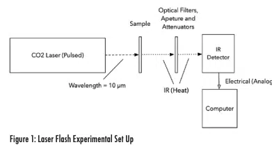
In the laser flash technique, a pulse of laser light is used to rapidly heat the front surface of the sample of interest. As heat flows through the sample, the backside temperature rise is measured using an infrared detector. This temperature rise is fitted to a one-dimensional heat flow model that calculates the thermal diffusivity (α). The thermal conductivity (κ) is then determined by using Equation (1) below
where Cp is the materials heat capacity and ρ is density. If the laser pulse heating time is short compared to the backside temperature rise, and the heat flow is 1- dimensional, this model will give an accurate measurement of the material’s thermal conductivity.
A schematic of the laser flash set up is shown in Figure 1.
Here, we utilize a CO2 pulsed laser with a pulse length of 0.5 µsecond and a HgCdTe cooled IR detector.
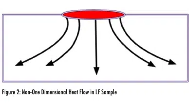
As described in ASTM E1461-071 , one of the limitations of laser flash is when heat flow through the sample is not purely one-dimensional. Even in a simple geometry, more complex heat flow can occur after laser pulse heating if heat flows laterally toward the sample edges (where convection can occur) in addition to flowing through the thickness of the sample. This is illustrated in Figure 2.
If this type of non-1D heat flow occurs, the temperature rise at the backside of the sample will take longer to occur, and the fit to a 1D model will lead to a lower estimated sample thermal conductivity than the actual value.
This issue is exacerbated when measuring samples with complex geometries or “real world” samples that may include heat sinks or other complicating structures.
To extend the laser flash technique to samples with more complex heat flow patterns, we have utilized Finite Element thermal simulations to model the laser flash results. As shown in this article, this approach allows us to determine the thermal conductivity of critical interfaces or material layers with unknown thermal properties within complex “real world” structures.
For simple geometries, Finite Element simulation gives the same results as a conventional 1D heat flow model. However, the Finite Element model can be extended to systems with complex heat flow induced by heat sinks and to samples with significant lateral heat flow. These are situations where the 1D model would not give accurate results.
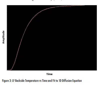
Description of the Laser Flash Technique As mentioned previously, the laser flash measurement uses a short laser pulse that is absorbed on the front surface of the sample. This pulse produces a very thin heated layer on the front surface that then diffuses through the sample. An IR detector focused on the backside of the sample detects the temperature rise as a function of time. This curve is the critical data output from the laser flash measurement.
In a conventional test, this temperature profile is modeled with a solution to the 1-dimension heat flow equation. This solution is shown in Equation (2), where t is the time after the laser pulse, T(t) is the time-dependent temperature of the backside of the sample, T(0) is the temperature of the sample backside at t=0, Tm is the maximum temperature of the sample backside, L is the sample thickness, and α is the thermal diffusivity1 .
Figure 2 shows an example of this backside temperature rise (red) and the fit to the 1D analytical model (white) for a graphite thermal conductivity NIST standard with thermal conductivity of 91 W/mK. An analytical solution to the 1D heat flow equation is used to fit the temperature vs. time curve to determine the thermal diffusivity, α. Thermal conductivity is then calculated using Equation (1). The material’s heat capacity Cp is determined using Differential Scanning Calorimetry (DSC).
In addition to homogeneous materials, this approach can also be applied to layered structures2 . In this case, the same type of measurement is made through the layered stack. For a three-layer structure, if the thermal diffusivities of two of the three materials are known, the diffusivity of the third material can be determined. In this case, the analytical equation for one-dimensional heat flow through a three-layer structure is used. In electronic applications, this can be very useful for determining the thermal impact of die attach or thermal interface materials (TIMs).
Finite Elements Modeling
Finite element modeling is a numerical technique that divides a body into smaller cells utilizing a mesh and then solves for properties such as mechanical stress and heat transfer at each of these finite locations. The finite element approach utilizes 3D models of the structure of interest and can thus account for complex shapes and structures that are very difficult to analyze using a single global analytical solution as is typical in conventional laser flash analysis. Commercial software programs such as SolidWorks® (utilized here) routinely perform this type of analysis.
Application to Layer Structures
In the first example, we apply both the conventional analytical 1D heat flow model and the finite element approach to laser flash measurement of an Ag epoxy die attach material sandwiched between a GaAs die and a Mo substrate. In this measurement, the thermal conductivity of the GaAs and Mo are known (measured independently), the temperature profile of the backside of the Mo is measured in the laser flash experiment, and the unknown thermal conductivity of the die attach epoxy is then determined.
In this case, heat flow through the sandwich structure is 1 dimensional, so the 1D analytical solution is a valid modeling approach. The purpose here is to show that the 1D model and the finite element model have good agreement for a situation where both are applicable.
1D Heat Flow Analytical Model Results
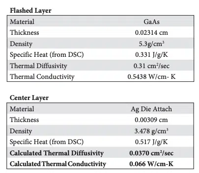
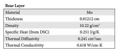
The results of the analytical model, as well as the material parameters input to the model, are shown below. The 1D analytical model, which analyzes 1D heat flow through a 3-layer structure, solves for the thermal diffusivity of the die attach epoxy.
The 1D model calculated thermal conductivity of the Ag epoxy layer, which would include any interfacial thermal resistance, as 6.6 W/mK (calculated thermal conductivity of the Center Layer in the table).
Finite Element Model Results
A finite element model was created for the same structure. Inputs to the model included the laser pulse width of 0.5 µsec with 10 Joules of energy and the measured backside temperature vs. time after the pulse was absorbed.
The finite element model had the best fit to the measured backside temperature profile data when the thermal conductivity of the Ag epoxy layer was 6.7 W/mK. This value is very close to the 1D analytical model result of 6.6 W/mK.
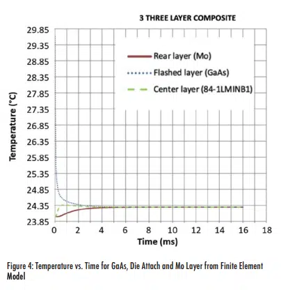
An additional benefit of the finite element model is that we can also find the temperature profile for each layer as the heat diffuses, as shown in Figure 4. This figure shows the initial heating of the front GaAs surface from room temperature up to about 29.85°C, transferring heat in the first 0.001 seconds to the epoxy layer with the eventual slower heating of the backside Mo layer.
The good agreement between the analytical model for 1D heat flow and the Finite Element model in a case that is applicable to both models validates the use of the Finite Element approach to model laser flash measurements. Next, we will apply this to a more complex structure where the analytical model cannot be used.
Application to Complex Structure
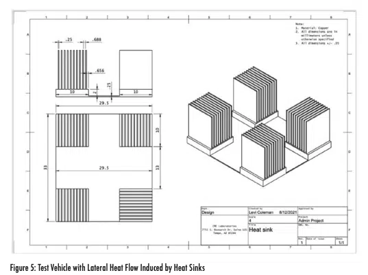
Now we will apply the finite element analysis of laser flash to a complex geometry where the simple analytical model approach cannot be applied. We have constructed a test vehicle consisting of Cu substrate with 4 soldered heat sinks on each corner, as shown in the drawing above.
The laser pulse is incident on the center of the top surface and the temperature of the Cu substrate backside is measured vs. time. Before constructing this test vehicle, we measured the thermal conductivity of the bare Cu foil. The thermal conductivity of the Cu foil without a heat sink attached was 292 W/mK.
If the temperature change on the backside of the Cu foil in the heat sink structure is analyzed with the 1D heat flow model, the thermal conductivity of the Cu substrate is calculated to be 200 W/mK, which is much lower than the actual value of 292 W/mK. This drops to 160 W/mK if air is circulated over the heat sinks because of the substantial lateral heat flow toward the heat sinks. Lateral heat movement reduces the rate that the backside of the Cu heats up, which leads to a lower calculated thermal conductivity using a model that does not account for it.
With a finite element model of this more complex geometry, we can account for the lateral heat flow and convection from the heat sink surfaces. Inputs to this model are the laser power, laser pulse duration, spot size, convection coefficient from the heat sink surfaces, and the measured backside temperature rise as a function of time after the pulse is incident on the top surface of the Cu substrate.
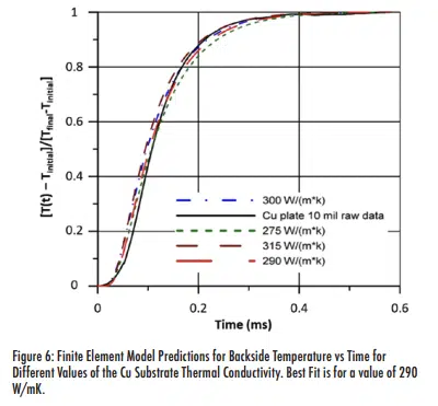
Figure 6 shows the finite element results for the backside temperature rise, along with the measured results, for various values of the Cu substrate layer thermal conductivity. The measured data is the solid black line.
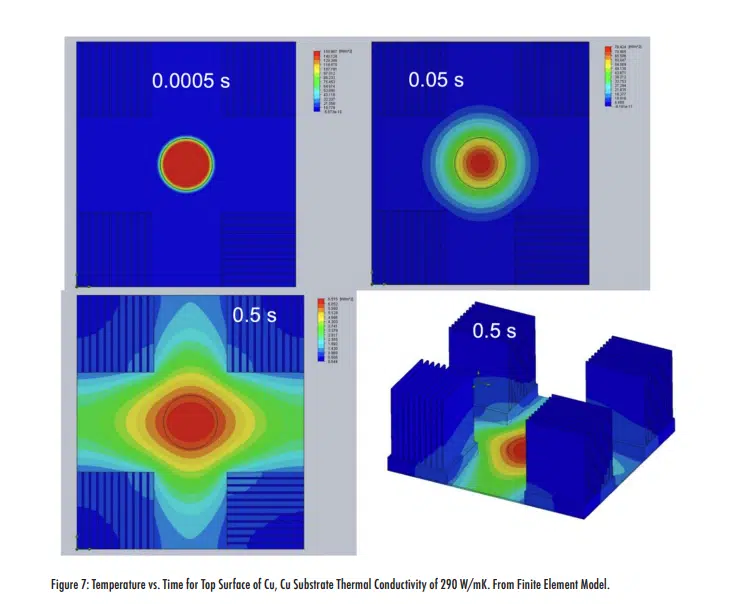
The best fit to the actual data is a Cu thermal conductivity of 290 W/mK, which is very close to the measured value of 292 W/mK. Utilizing the finite element model with this value for the Cu thermal conductivity, we can also determine the lateral heat flow as a function of time. This is shown for the top surface in the Figure 7.
This example illustrates how laser flash can be used to determine the thermal conductivity of an unknown material or interface in a complex structure where non-1D heat flow occurs. As a result, this combination of laser flash and finite element modeling greatly expands the usefulness of the laser flash measurement to “real world” geometries with complicated heat flow patterns.
Below are listed some areas of potential applications of this approach:
- Complex, irregular geometries such as geological samples
- Electronic structures with heat sinks and various heat conducting patterns as would be present in circuit board or complex packages
- Thick samples where heat flow to sample edges with subsequent convection is occurring
- Large format samples, particularly of high thermal conductivity material, where lateral heat flow is always going to be a consideration
- Complex sandwich structures with multiple layers where analytical solutions to 1D heat flow are not available
Summary
This article has shown how the combination of finite element modeling and the laser flash measurement technique can allow the thermal conductivity of materials in complex structures with non-1D heat flow patterns to be determined. This overcomes one of the major limitations of the laser flash technique.
References
1 ASTM E1461-07, Standard Test Method for Thermal Diffusivity by the Flash Method, ASTM International, January 2008
2 See, for example, Thermal Diffusivity of Dispersed and Layered Composites, PhD Thesis, Tsu-Yum Richard Lee, Purdue University, 1977

