ABSTRACT
Graphite foils with ultra-high spreading capacity and insulation sheets with ultra-low thermal conductivity were combined in a thermally stressed Google Pixel 3XL (Pixel) to significantly increase steady-state system performance, while maintaining safe device touch (skin) temperatures (TS ), as compared to the out-of-the-box device configuration. Four unique thermal solutions of comparable thickness (~350 µm) were fabricated and subjected to thermal stress testing in the Pixel via 3DMark—Sling Shot Extreme. Steady-state touch temperatures were reduced by up to 3.2°C with <1°C increase in max junction temperature (TJ ) as compared to single-component thermal solutions of graphite, insulation, and air. The composite yielding the greatest TS reduction was utilized to demonstrate an increase in steady-state system performance, while maintaining a surface temperature suitable for user safety. The steady-state 3DMark—Sling Shot Extreme benchmark score increased from 3,401 to 3,823 resulting in a 12.4% increase in steady-state system performance.
The enhanced device performance was linked with material properties by means of steady-state heat flow and thickness testing for through-plane thermal conductivity of insulation, and thermal diffusivity testing for in-plane thermal conductivity of graphite.
KEYWORDS
Graphite, ultra-high spreading capacity, insulation, ultra-low thermal conductivity, composite, heat spreader, thermal conductivity, thickness, surface touch (skin) temperature, hot spot, junction temperature, ambient temperature, steady-state, Google Pixel 3XL (Pixel), system on chip (SoC), 3DMark—Sling Shot Extreme, benchmark score, system performance, user safety.
NOMENCLATURE
k thermal conductivity (W/m·K)
t thickness (mm, µm)
TS surface touch (skin) temperature (K, °C)
TJ device junction temperature (K, °C)
∆T change in temperature (K, °C)
q” heat flux (W/m2 )
R” thermal resistance (K·m2 /W)
t·∆T intrinsic heat spreading capacity (µm·K)
INTRODUCTION
Thermal spreaders (graphite) and insulators (air, polymers) have been widely and commonly used to address heat challenges in the mobile electronics industry. As the trends for higher power processing and thinner form devices become standard requirements, mobile electronics continue to face a more pressing issue of user safety by means of the surface touch (skin) temperature (TS ).
The Underwriters Laboratories (UL) guidance for TS is based on direct skin contact for specific temperatures and durations, [1] and is accepted across the mobile electronics industry. Where passive thermal solutions have previously been able to reduce the TS below specification, many of the commonplace materials such as air and synthetic graphite are facing technical limitations [2]. In the absence of a thermal solution that maintains system performance, one widely practiced solution is power throttling of the processor, which may reduce system power by up to 50% [3].
In thin mobile electronics with relatively low temperatures (<100°C) and no active cooling, conduction is the primary mode of heat transfer inside the device [4]; internal convection and radiation are considered negligible in comparison and not discussed further in this work.
Fourier’s Law of One-Dimensional Conduction Heat Transfer, shown in Equation (1), states that the theoretical change in temperature (ΔT) is directly proportional to the thermal resistance (R”) of the heat transfer medium.
Assuming heat flux (q”) in a given system is constant, ΔT is driven by R”, which is defined as the ratio of thickness (t) to conductivity (k).
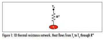
Combining and rearranging Equations (1) and (2), TS can be viewed as a function of the junction temperature (TJ ), t, k, and q”, which is shown in Equation (3) and the accompanying one-dimensional resistance network (Figure 1). In a constrained system with constant q” and t, TS can be reduced by lowering k.
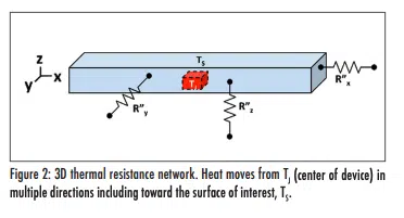
When a system is expanded into three dimensions of heat transfer (Figure 2), planar heat spreading can be an integral contributor to the resulting TS. Both in-plane and through-plane conductivities deliver significant contributions to the resultant spreading of heat in a material of given thickness and area. Combining ultra-low (through-plane) conductivity insulation with ultra-high spreading capacity graphite yields a thermal composite solution with exceptional heat spreading performance compared to existing materials used for thermal management in thin mobile electronics.
MATERIAL SELECTION
GORE® thermal insulation (W. L. Gore & Associates, Inc.) is an insulating material (“the insulation”) exhibiting ultra-low thermal conductivity, below that of air, in thin sheet form (100 μm and 250 μm). NeoNxGen™ thermal management solutions (NeoGraf Solutions, LLC) includes a thick foil graphite (70 μm to 270 μm) displaying ultra-high intrinsic heat spreading capacity (“high-performance thick graphite”).
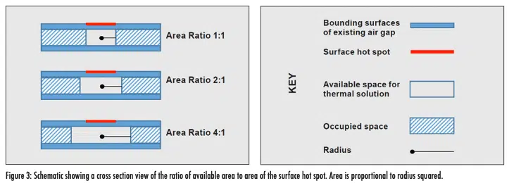
Individual layers of insulation and graphite may separately provide a reduction in TS when placed between a heat source and the surface of interest. Insulation alone is an optimal solution when the ratio of available area to area of the surface hot spot is approximately one-to-one. While insulation is relatively isotropic, graphite exhibits highly anisotropic behavior, favoring thermal conduction in the plane of the material. This utility becomes impactful for TS reduction when the ratio of available area to area of the surface hot spot approaches two-to-one or greater; in these system architectures insulation can be combined with graphite to enhance its effective heat spreading capacity. A schematic of the ratio of available area to area of the surface hot spot is illustrated in Figure 3.
INSULATION THERMAL CONDUCTIVITY CHARACTERIZATION
The insulation is characterized by its distinctively low thermal conductivity, <0.020 W/m·K, due to a conduction heat transfer phenomenon known as the Knudsen Effect. The Knudsen Effect explains that when the pore diameter in a medium is smaller than the mean free path of air (approximately 70 nm), the path of heat transfer through this medium is disrupted, relative to the path of heat transfer through air in free space [5]. This principle is often applied through the use of aerogels due to their morphology of high porosity with small pore diameters. The uniqueness of this insulation appears in the form of a homogeneous aerogel structure with ultra-low (and consistent) thermal conductivity and precise thickness resulting in a reliably high thermal resistance. Comparatively, the thermal conductivity of free air at room temperature is 0.026 W/m·K and it increases non-linearly with temperature (0.028 W/m·K at 50 °C), [6] which can result in variable and insufficient thermal resistance at elevated temperatures (>50°C) in mobile electronics.
The through-plane thermal conductivity of this insulation is determined by measuring thermal resistance using a heat flow method (TA-Fox 50) and material thickness method (Instron-5565), following guidance from ASTM C518-17 [7] and ASTM F36-15 [8, 9].
GRAPHITE THERMAL CONDUCTIVITY CHARACTERIZATION
Graphite is used for spreading heat due to its inherently high conductivity in the planar direction and relatively low conductivity in the through-plane direction. Synthetic graphite thickness ranges from less than 25 μm (~1,500 W/m·K) up to 100 μm (~600 W/m·K), with in-plane thermal conductivity trending inversely to thickness. Layering thin sheets of high conductivity graphite is a potential way to improve heat spreading capacity at higher thicknesses, though this often leads to inconsistencies in thermal performance as well as challenges in manufacturing. High-performance thick graphite foils prove to have the thermal conductivity benefits of thin synthetic graphite, up to 1,100 W/m·K in-plane, at single-layer thicknesses similar to that of natural graphite. The through-plane conductivity is comparably ~3.5 W/m·K for each grade of graphite.
The in-plane thermal conductivity of this graphite is determined by measuring thermal diffusivity using one of two methods: an Angstrom instrument [10] or a Thermowave Analyzer (Bethel TA-33) [11].
EXPERIMENTAL METHOD: GOOGLE PIXEL 3XL—3DMARK STRESS TEST
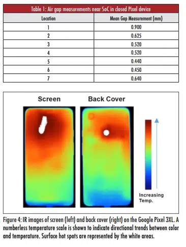
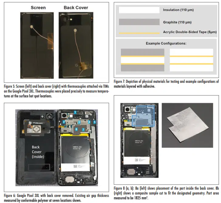
An off-the-shelf Google Pixel 3XL (“Pixel”) was purchased and modified to allow for constant power stressing without thermal throttling. UL’s 3DMark—Sling Shot Extreme was chosen for testing as it is a widely-accepted benchmark used to score the physics (CPU) and graphics (GPU) of high-end smartphones [12]. In order to achieve steady-state test results, the professional version of 3DMark was purchased and installed on the Pixel to enable infinite looping of the 90-second Sling Shot Extreme benchmark test. All testing was conducted in a still air environment with tightly controlled ambient temperature and humidity. Parameters available for measuring include: surface point temperatures via thermocouples, images via IR camera (Fluke, Model Ti55), internal component temperatures (CPU, GPU, etc.) via built-in thermistors, CPU and GPU clock frequencies, and system performance via Sling Shot Extreme benchmark score. An initial stress test was run in the out-of-box condition with IR imaging (Figure 4). Hot spot locations were identified and chosen for placement of thermocouples via TIMs (Figure 5).
The Pixel back cover was removed by means of heating and breaking adhesive. A conformable polymer was placed inside the back cover at seven different locations near the SoC (Figure 6) to determine the space available for a thermal solution; the back cover was then replaced to compress the polymer into the existing air gap at each location. The back cover was removed again and thickness at all locations was measured via snap gauge on the compressed polymer. This process was repeated twice more and all thickness measurements per location averaged. Thickness means are detailed in Table 1.
In order to avoid mechanical compression in Locations 5 and 6, a nominal thickness of 350 μm was chosen for all thermal solutions. Physical materials for testing include 110 μm insulation sheets, 110 μm graphite foils, and 5 μm acrylic double-sided tape. Materials and example configurations are illustrated in Figure 7.
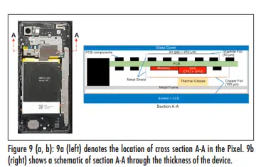
The part geometry, shown in Figure 8, was chosen to maximize area with no or minimal disruption to internal components. For simplicity, only configurations with uniform thickness and layers with identical shape and area were considered. Further optimization in layer thicknesses and sizes are possible to achieve form, fit, or functional goals. A cross section schematic through the thickness of the phone is depicted in Figure 9.
EXPERIMENTAL RESULTS
Back Cover Touch Temperature Study
Device test configurations are titled A, B, C, D, and E with A as the control scenario. The CPU and GPU frequencies were set at 2,169.6 MHz and 675 MHz, respectively. Frequencies were recorded and verified at the end of each test run. Benchmark scores were recorded to show performance consistency across all test runs. Ambient temperatures in the still-air environment were held between 21.6°C and 21.8°C for all testing. All configurations were tested three times to steady-state (>90 minutes) in a randomized experiment.
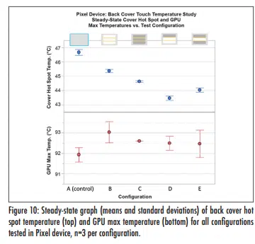
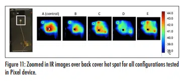
After each test run, the Pixel was cooled down to idle operating temperature and opened up to setup the next test run. The steadystate back cover hot spot touch temperatures and GPU max temperatures are shown in Figure 10. IR images of the back cover are shown in Figure 11. Depictions, thicknesses, and measured outputs (means and standard deviations) for all tested configurations are detailed in Table 2.
All test configurations produced unique back cover touch temperatures with high precision, and all were distinctly lower than the control (Configuration A). Configuration D presented the greatest back cover touch temperature reduction at 3.2°C below the control. Configurations E, C, and B reduced the back cover touch temperature by 2.7°C, 2.1°C, and 1.3°C, respectively. Screen temperatures increased from the control by <1°C for all configurations tested and <0.5°C for composite configurations. CPU and GPU temperatures increased from the control by <1.5°C for all configurations tested and <1°C for composite configurations.
System Performance and Safe Touch Temperature Study
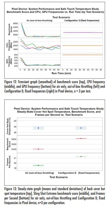
A continuation study was created to determine the allowable system performance increase when enabled by insulation-graphite composites; Configuration D was selected for this study. Outof-box throttling conditions were restored to the Pixel and all thermal solutions were removed, leaving air only. The back cover touch temperature was measured during steady-state power throttling and recorded for three test runs. Configuration D was installed and frequencies were set to match the steady-state cover temperature from the throttled control runs. The appropriate frequencies for testing were determined to be 1,996.8 MHz and 596 MHz for the CPU and GPU, respectively. Frequencies, cover hot spot temperature, benchmark score, and frames per second were measured and compared between the two test scenarios. A smoothed plot of benchmark score, CPU frequency, and GPU frequency vs. run time for all six test runs is displayed in Figure 12. Mean steady-state cover temperature, benchmark score, and frames per second are shown in Figure 13. Details are summarized in Table 3.
The mean steady-state cover touch temperature achieved during out-of-box throttling is 38.7°C in the controlled test environment at 21.7°C; this temperature is related to UL 62368-1 mobile electronics touch (skin) temperatures at prolonged durations. In this scenario, the mean steady-state benchmark score and fFrames per sSecond are 3,401 and 19.5, respectively. When Configuration D is placed inside the back cover, the benchmark score is increased to 3,823 and frames per second increased to 21.3, marking a ~12% increase in system performance, while maintaining the safe surface temperature limit set for the outof-box throttling condition.
SUMMARY/CONCLUSION
Graphite foils with ultra-high spreading capacity and insulation sheets with ultra-low thermal conductivity were combined in a modified Google Pixel 3XL to reduce surface touch (skin) temperatures, while minimally impacting the device junction temperature, compared to solutions of air, insulation alone, and graphite alone. One insulation-graphite composite configuration was further tested in comparison to an out-of-box condition, and was found to improve system performance in a UL benchmark test by ~12% while maintaining the out-of-box cover surface temperature limits.
The results demonstrated by insulation-graphite composites in Pixel device testing can be explained by the exceptional thermal properties exhibited by these two materials. Through-plane thermal conductivity for the insulation was measured and calculated using a heat flow method on a TA-FOX 50, and a thickness method on an Instron-5565. In-plane thermal conductivity for high-performance thick graphite was measured and calculated using a thermal diffusivity method on a Bethel TA-33.
High-performance insulation-graphite composites may have vast utility in the high-powered, thin architectures of mobile electronics. It is important to note that each mobile electronic system may exhibit unique thermal challenges given system power, available space, and/ or other constraints. For this reason, the optimal design configuration (area, thickness, orientation) should be determined by virtue of device-specific simulation and testing. The case study presented in this paper demonstrates the enhancement of thermal management in mobile electronics; two leading-edge materials, when combined, yield a thermal solution with performance greater than the sum of its parts.
REFERENCES
1. UL, UL. “62368-1: 2017 Audio/video, information and communication technology equipment – Part 1: Safety requirements.” (2017).
2. Wagner, Guy, and William Maltz. “Thermal management challenges in the passive cooling of handheld devices.” 19th International Workshop on Thermal Investigations of ICs and Systems (THERMINIC). IEEE, 2013.
3. Wagner, Guy R. “A study of the maximum theoretical power dissipation of tablets under natural convection conditions.” 20th International Workshop on Thermal Investigations of ICs and Systems. IEEE, 2014.
4. Luo, Zhaoxia, et al. “System thermal analysis for mobile phone.” Applied Thermal Engineering 28.14-15 (2008): 1889-1895.
5. Bi, C., G. H. Tang, and W. Q. Tao. “Prediction of the gaseous thermal conductivity in aerogels with non-uniform poresize distribution.” Journal of Non-Crystalline Solids 358.23 (2012): 3124-3128.
6. Kannuluik, W. G., and E. H. Carman. “The temperature dependence of the thermal conductivity of air.” Australian Journal of Chemistry 4.3 (1951): 305-314.
7. ASTM C518 – 17 Standard Test Method for Steady-State Thermal Transmission Properties by Means of the Heat Flow Meter Apparatus
8. ASTM F36 – 15 Standard Test Method for Compressibility and Recovery of Gasket Materials
9. LaserComp, Inc.. “Tests of thin samples stacked (using FOX50 instrument)” Application Note AN-TSS © 2008 (October 23).
10. Wagoner, G., Skokova, K.A. and Levan, C.D., “Angstrom’s Method for Thermal Property Measurements of Carbon Fibers and Composites”, The American Carbon Society, CARBON Conference, 1999.
11. Beyerle, R., Smalc, M., Kantharaj, R., Taylor, J., Norley, J., “Thermal Diffusivity Characterization of Thick Graphite Foils”, 35th Semi-Therm Symposium, 2019.
12. 3DMARK® Technical Guide, Underwriters Laboratories, Fremont, CA, 2020.


