Introduction
Vapor chambers are passive two-phase devices used to spread heat from localized hotspots to larger surface areas. The device utilizes the latent heat of evaporation of an internal fluid to passively transport heat from the evaporator (heat source) to the condenser (heat sink) across very low-temperature drops. Condensed liquid returns to the evaporator from the condenser via capillary pumping by an internal wick. Due to the mass, momentum, and energy transfer coupling via phase-change processes at interfaces between the wick and vapor core, direct numerical simulation of vapor chamber transport [1–3] is a computationally expensive and complex endeavor. It is therefore of interest for thermal designers to have access to more simplified methods of representing vapor chambers in numerical transport simulations that predict thermal performance without a significant compromise in accuracy.
Effective Representation of a Vapor Chamber as an Anisotropic Material As an alternative to direct simulation of the internal flow dynamics, vapor chamber thermal transport can be predicted by treating the vapor core as a thermal conduction block with appropriately assigned effective thermal properties (conductivity and specific heat). These effective properties must be chosen to accurately represent the underlying vapor flow dynamics and temperature drops. Vapor chambers are known to have inherently anisotropic heat-spreading behavior. A seminal formulation for the effective in-plane thermal conductivity of a vapor chamber based on the vapor core saturation temperature drop was given by Prasher [4]:
where hfg is the latent heat of vaporization, P is the vapor pressure, ρ vapor density, hvap is the vapor core thickness, R is the specific vapor gas constant, µ is the vapor viscosity, and Tsat is the average vapor core saturation temperature. It is important to note that Equation (1) has a strong temperature/pressure dependence as it is not an intrinsic material thermal conductivity, and hence the vapor properties (hfg, ρ and µ) and P are calculated at Tsat. Because Tsat is not known a priori, Tsat is a good initial guess of the vapor chamber condenser temperature.
An alternative formulation is required for the effective crossplane thermal conductivity of the vapor core. We caution against assuming that the vapor core can be represented as an isotropic material, as use of Equation (1) as the effective cross-plane thermal conductivity leads to erroneous temperature predictions [5]. Similarly, the vapor (gas) material thermal conductivity is not an acceptable alternative for the cross-plane thermal conductivity. A more accurate physical representation of the anisotropic nature of vapor core transport was developed in our recent work [5] by comparing the vapor core transport equation to a heat diffusion equation. Effective properties are thereby derived to ensure that, if the vapor core is treated as an anisotropic solid conduction block, the transient and steady-state temperature response would be the same as if directly solving the vapor transport equations [3]. This leads to the same expression for in-plane thermal conductivity as in Equation (1) and a new expression for the cross-plane thermal conductance per unit length:
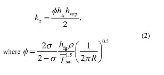
and σ is the accommodation coefficient while the rest of the nomenclature is the same as for Equation (1). Note that Equation (2) is not an intrinsic material thermal conductivity, but rather is a function of vapor thermophysical properties and vapor core thickness. Similar to Equation (1), the vapor properties in Equation (2) should be calculated at Tsat. For accurate transient predictions, the effective thermal capacity of the vapor core can be modeled by taking effective density and specific heat properties that are equal to that of the vapor (gas) thermophysical properties as

where ρ is the vapor density and Cp is the vapor specific heat calculated at Tsat.
Details of the derivation of these effective parameters are available in Ref. [5]. Extensive verification has also been conducted to ensure that using these effective anisotropic vapor core properties in numerical simulations results in the same thermal predictions as an experimentally validated vapor chamber model [3] over a range of cases. The reader is also encouraged to refer to Ref. [5] for details regarding estimates of the error associated with using these parameters that is associated with necessary simplifying assumptions that neglect convective vapor transport (only diffusive transport is considered) and linearization of the Clausius–Clapeyron equation. Lastly, we note that vapor chamber operation is subject to several transport limits, such as the capillary limit, which must be calculated separately; these effective anisotropic properties apply to operation below all such limiting conditions.
Implementation in Numerical Conduction Solvers
Proper implementation of the effective anisotropic conduction parameters given by Equations (1-3) into commercial numerical conduction solvers requires care. This is due to the nature of the cross-plane parameter being a conductance per unit lengthrather than a simple analog for material thermal conductivity. In addition to assigning the correct anisotropic properties, the vapor core must be meshed with a single element across its thickness. This ensures that only a single computational node exists along the thickness of the vapor core at a given in-plane location, and allows for solving a cross-plane-averaged temperature at each cell in the vapor core as assumed in the derivation of the effective anisotropic properties. Using more than one computational node across the thickness of the vapor core will lead to an erroneous prediction. The vapor core must be sandwiched between material layers that represent conduction in the wick and the wall of the vapor chamber. These layers can be assigned the correct thermophysical properties (conductivity, density, and specific heat) and are typically assumed to be isotropic.
This guide does not cover calculation of the effective properties of porous wick structures, but readers are directed to Ref. [6], which offers simple expressions to calculate wick thermal conductivity as a function of the wick porosity and geometric parameters.
The following section provides an example implementation of these effective anisotropic properties into a numerical conduction solver. The example considers a specific thermal analysis software tool (Icepak), but the approach is translatable to any finite-volume numerical conduction solver that allows controlled generation of the single-cell-thick vapor core mesh and custom assignment of anisotropic properties.
Demonstration Case
Geometry, model setup, and boundary conditions
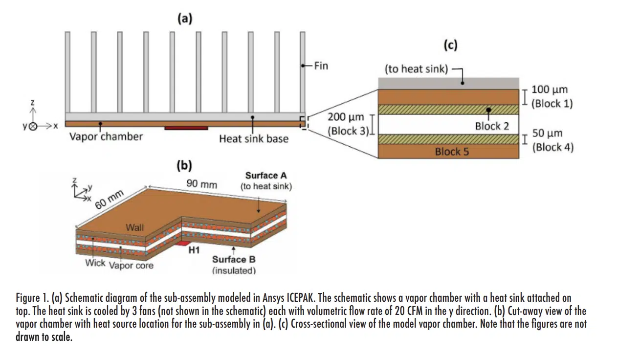
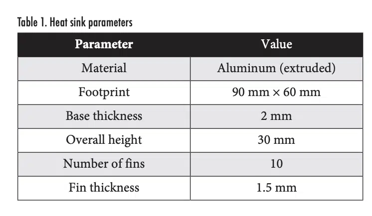
Figure 1(a) shows the vapor chamber and heat sink assembly that is considered for demonstrating the implementation of the effective anisotropic properties approach to simulate vapor chamber thermal transport. A heat sink is attached to the top surface of the vapor chamber, both having a 90 mm × 60 mm footprint. Table 1 summarizes the heat sink design as modeled using the “Heat Sink” tool in ANSYS Icepak. The heat sink is cooled by three fans (20 CFM each at 20°C ambient temperature) specified using the “Fans” tool in ANSYS Icepak, which allows the user to set the fan type (“intake”), geometry (“circular”), and flow rate.
Figure 1(b) shows a cut-away view of the vapor chamber geometry used for the demonstration. The top surface of the vapor chamber (Surface A) is connected to the heat sink. The bottom surface of the vapor chamber (Surface B) has a centrally located 10 mm × 10 mm heater (labelled H1) with input power of 15 W; the rest of this bottom surface is insulated.
The vapor chamber is implemented in the model as a connected stack of five rectangular blocks: one for the vapor core and two each for the walls and wick layers, as shown in Figure 1(c). The footprint of each block matches the heat sink, and the thicknesses are based on the region the blocks represent (wall blocks 1 and 5 are 100 µm in thickness, wick blocks 2 and 4 are 50 µm, and the vapor core block 3 is 200 µm). Copper thermal properties are selected for the wall material, while custom solid-material properties are defined for the wick and the vapor core. The thermal conductivity of the wick material is set as 40 W/m-K for this demonstration.
For the vapor core, the effective thermal properties are calculated from Equations (1-2). It is important to determine the vapor properties used to evaluate these temperature-dependent effective thermal properties at the average vapor core saturation temperature. This temperature can be guessed or approximated in advance based on the heat sink thermal resistance and then iteratively updated using the predictions. For this example, the properties of water are evaluated at 32°C, resulting in kx = ky = 11,019 W/m-K and kz = 2.7 W/m-K for the vapor core (using an accommodation coefficient value of σ = 0.03 for water). These vapor core effective properties can be defined in ANSYS Icepak by selecting a solid material type with a custom orthotropic conductivity, setting the in-plane property (kx, ky) to 11,019 W/m-K and the out-of-plane property (kz) to 2.7 W/m-K, using the coordinate system shown in Figure 1(b).
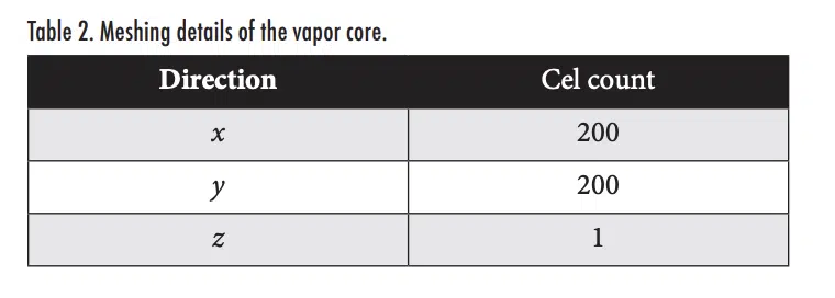
While meshing the vapor chamber, we reiterate that it is critical to ensure that the mesh of the vapor core has just a single cell across the z-direction, as shown in the snapshot of the mesh shown in Figure 2. As explained earlier in Section 3, this requirement arises from implementing the effective thermal conductance as a material thermal conductivity in a conduction solver. In ANSYS Icepak, single-cell meshing of the vapor core thickness can be achieved by editing the meshing parameters per-object, and setting the vapor core block to request a z-direction mesh count of 1. Most commercial conduction software has similar provisions for custom-defined mesh constraints. The mesh resolution in the in-plane directions and across the thickness of the other blocks in the domain should follow standard simulation best practices, including confirmation of mesh independence. For purposes of this demonstration, the wall and wick have three and four cell counts across their thicknesses, respectively, as shown in Figure 2. The cell counts of all layers in the vapor core are summarized in Table 2.
Demonstration Results
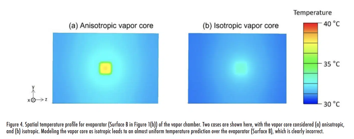
Figure 3(a) shows the steady-state temperature profile across the vapor chamber evaporator and condenser surfaces (along the line a-a indicated in the inset) computed by representing the vapor core as an anisotropic conduction block (kx = ky = 11,019 W/m-K, kz = 2.7 W/m-K) as recommended. For comparison, the same temperature profiles are plotted in Figure 3(b) when assuming the vapor core to be isotropic (kx = ky = kz = 11,019 W/m-K). When assuming an isotropic vapor core, the maximum temperature on the evaporator at the location of heat input is grossly under-predicted. Considering an ambient air temperature of 20ºC, this under-prediction of the maximum evaporator temperature by 6ºC corresponds to a 33% error in total thermal resistance of the assembly. Figure 4 compares the spatial temperature distribution across the evaporator surface for a vapor core represented using anisotropic (Figure 4(a)) versus isotropic (Figure 4(b)) conduction blocks. It is observed that the evaporator surface temperature for the unphysical representation as an isotropic vapor core is unrealistically uniform compared to the anisotropic vapor core. This demonstration highlights the importance of representing the vapor core with effective anisotropic thermal properties to correctly simulate the physics of vapor chamber transport and predict temperature distributions.
Conclusions
This article provides easy-to-calculate effective properties that allow for prediction of the thermal response of a vapor chamber by representing the vapor core as an anisotropic conduction block. Thermal system designers can thereby simulate vapor chambers, either as standalone devices or within a system, without resorting to complex and computationally expensive direct simulation of the vapor transport. A guide to implementation of these effective properties into numerical conduction solvers is provided, and users of the technique should pay special attention to the following:
- The effective anisotropic properties presented here are derived from an analogy between a simplified physical vapor chamber transport model and the transient heat diffusion equation. Their accuracy is subject to the same assumptions made in the original vapor chamber transport modeling, with further discussion and error bounds provided in Ref. [5].
- The single-cell-thick meshing guidelines for the vapor core should be strictly followed so that values calculated from the expression for kz in Equation (2) can be substituted as a cross-plane thermal conductivity in a numerical conduction solver.
- The intrinsic effective properties derived depend only on the working fluid properties and vapor core thickness, and are independent of the boundary condition. However, they are highly sensitive to the vapor core temperature and geometry of the vapor chamber and therefore must be recomputed for new cases and operating conditions.
References
[1] U. Vadakkan, S.V. Garimella, and J. Murthy, “Transport in Flat Heat Pipes at High Heat Fluxes From Multiple Discrete Sources,” ASME Journal of Heat Transfer, vol. 126, pp. 347–354.
[2] R. Ranjan, J.Y. Murthy, S.V. Garimella, D.H. Altman, and M.T. North, “Modeling and Design Optimization of Ultrathin Vapor Chambers for High Heat Flux Applications,” IEEE Transactions on Components, Packaging and Manufacturing Technology, vol. 2, 2012, pp. 1465–1479.
[3] G. Patankar, J.A. Weibel, and S.V. Garimella, “A Validated Time-stepping Analytical Model for 3D Transient Vapor Chamber Transport,” International Journal of Heat and Mass Transfer, vol. 119, 2018, pp. 867–879.
[4] R.S. Prasher, “A Simplified Conduction Based Modeling Scheme for Design Sensitivity Study of Thermal Solution Utilizing Heat Pipe and Vapor Chamber Technology,” Journal of Electronic Packaging, vol. 125, 2003, p. 378.
[5] K. Baraya, J.A. Weibel, and S.V. Garimella, “An Effective Anisotropic Properties-Based Representation of Vapor Chambers,” IEEE Transactions on Components and Packaging Technologies, vol. 11, 2020, pp. 51–56.
[6] D.S. Smith, A. Alzina, J. Bourret, B. Nait-Ali, F. Pennec, N. Tessier-Doyen, K. Otsu, H. Matsubara, P. Elser, and U.T. Gonzenbach, “Thermal Conductivity of Porous Materials,” Journal of Materials Research, vol. 28, 2013, pp. 2260–2272.
