Overview
Accurate modeling of thermal networks requires that all relevant modes of heat transfer, including advection, be included. Otherwise, component temperatures may be under- or over-estimated. This article presents a method for systematically including advection in one-dimensional (1D) thermal networks, via the use of unidirectional elements in the thermal network equation. This method can be expanded for use in larger multi-node thermal networks that use Excel, Mathcad, or MATLAB for automated assembly of conductance arrays.
Nomenclature
q Heat rate (W)
ṁ Mass flow rate (kg/s)
Cp Specific heat (J/kg°C)
Tout Fluid outlet temperature of the duct / heat sink (°C)
Tin Fluid inlet temperature of the duct / heat sink (°C)
Kadv Advective thermal conductance (W/ °C)
n number of nodes in a thermal network
Ti Temperature at node i (°C)
qi Heat load at node i (W)
Ki,j Conductance between node i and node j (W/°C)
Kair Advective conductance for air at a given mass flow rate (W/°C)
Cpair Specific heat of air (approximately 1000 J/kg°C)
Advection
Accurate modeling of thermal networks requires that we include all relevant modes of heat transfer:
• Conduction – diffusion of heat due to molecular motion
•Radiation – electromagnetic waves
• Convection – heat transfer due to motion of fluid (includes diffusion and advection)
• Advection – heat transfer due to bulk motion of a fluid
Practically speaking, when modeling heat transfer to a fluid (convection), we should include the effects of heating of the fluid itself (advection) in the thermal model. Neglecting advection completely will result in underestimating the temperature rise of a component. Including advection incorrectly will result in erroneous estimation of the temperature rise of a component. The heat transferred via advection to a fluid flowing through a duct or a heat sink is expressed in Equation 1:
Where q is the heat transported by the fluid (W), ṁ is mass flow rate of fluid in a duct (kg/s), Cp is the specific heat of the fluid (J/ kg°C), Tout is the fluid outlet temperature of the duct (°C), and Tin is the fluid inlet temperature of the duct (°C).
Equation 1 can be recast as an advective thermal conductance, in Equation 2:
Where Kadv is the advective thermal conductance (W/ °C), which is the inverse of the thermal resistance.
Options For Modeling Advection
A previous Electronics Cooling Magazine article [1] demonstrated multiple methods to model advection in a reduced order thermal model and the level of inaccuracy associated with each method. The least accurate (and simplest) method is to ignore advection and assume a component transfers thermal energy to air at the heat sink (or duct) inlet temperature. The most accurate (and complex) method is to use the Σ-NTU method, from heat exchanger analysis techniques. A method with acceptable levels of complexity and accuracy is to assume that the heat is rejected to the “midpoint temperature” of the air, meaning the average of the inlet and exit air temperatures in the sink. Another method from Steinberg [2} is to assume that the heat dissipating component rejects heat to the exit air temperature of the heat sink / duct. This last method is inherently conservative in that the exit air temperature of the sink is always higher than both the surface of the heat sink and the average air temperature in the sink, resulting in predicted component temperatures that are always higher than those predicted by the Σ-NTU or midpoint methods. As will be demonstrated by this article, it also has the advantage of being able to be folded easily into a multi-node network thermal model, as long as precautions are taken to properly implement the advection network elements.
Example
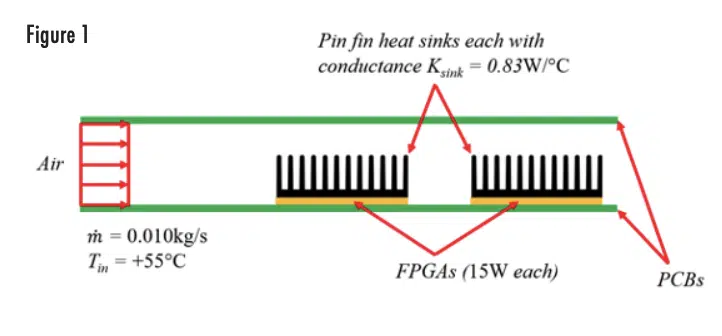
The following model demonstrates both the incorrect and the correct ways to implement advective thermal network elements. Figure 1 depicts a duct formed by two printed circuit boards (PCBs). Air at a temperature Tin = +55°C and a mass flow rate of ṁ=0.010kg/s enters the inlet of the PCB slot. The active side of one PCB has two identical components attached to it and each component has an identical heat sink bonded to it. The components are Field Programmable Gate Arrays (FPGAs), each dissipating 15W. The heat sinks each have a conductance Ksink = 0.83W/°C (thermal resistance Rsink = 1.2°C/W) for the flow rate used in this example.
Using the “exit temperature” advection approach described in the previous section, the calculation of component and air temperatures can be performed as follows:
1) The 0.010 kg/s of inlet air at +55°C is heated to +56.5°C by the first 15W component: 15W / 10.0W/°C + 55.0°C = +56.5°C
2) The front 15W component dissipates heat via convection to +56.5°C air, resulting in a front heat sink temperature of +74.6°C: 15W / 0.83W/°C + 56.5°C = +74.6°C
3) The air downstream of the front component at +56.5°C is heated to +58.0°C by the rear 15W component: 15W / 10.0W/°C + 56.5°C = +58.0°C
4) The rear 15W component dissipates heat via convection to +58°C air, resulting in a rear heat sink surface temperature of +76.1°C: 15W / 0.83W/°C + 58.0°C = +76.1°C
Even though the Σ-NTU method would yield the “exact” solution, for purposes of this discussion the preceding results will be referred to as the “correct” results since the intent is that the heat from a component is convected to the exit temperature of the heat sink or duct.
Thermal Network – Initial
The compact equation for calculating the temperatures in a thermal network can be seen in Equation 2:
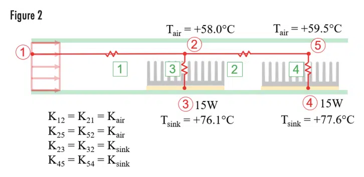
Where n is the number of nodes in the network, Ti is the temperature at node i (°C), qi is the heat load at node i (W), and Ki,j is the conductance between node i and node j (W/°C). Using this relationship, the example in the previous section can be set up as a thermal network problem as shown in Figure 2, and the nodal temperatures. Elements 1 and 2 are advective conductors with a value of Kair, which is calculated using Equation 2:
Since the mass flow rate ṁ=0.010kg/s and the specific heat of air Cpair = 1000J/kg°C, the value for Kair is determined to be 10W/°C.
Note that all the conductive elements in the model shown in Figure 2 are bilateral, meaning that they can conduct heat in either direction. Note also that the calculated component temperatures do not match the results from the “correct” solution. The network model returns a value of +76.1°C, where the “correct” solution was +74.6°C. Likewise, the network model returns a value of +77.6°C, for the second heat sink, where the “correct” solution was +76.1°C. The issue lies with the modeling of the advective conductors. For the heat sink conductors, thermal energy can flow either from a hot sink to cooler air, or from warmer air to a cooler sink. In the advective element the heat can only flow in one direction: in the direction of the fluid flow. Heat can’t flow upstream in the fluid from the duct exit to the entrance. The question is: how to model this in a thermal network?
Thermal Network – Final
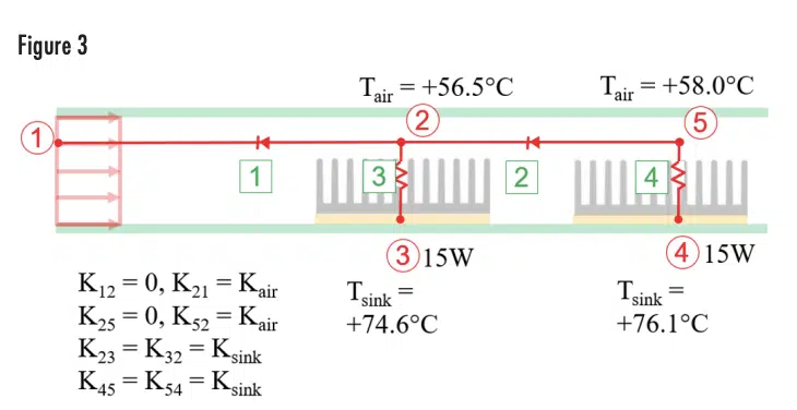
The way to achieve the correct solution in the thermal network model is by modeling the convection conductors as unidirectional, i.e., only able to pass heat in one direction. Figure 3 shows the advection conductors as diodes, which can only pass heat from the hot downstream node to the cooler upstream node, instead of resistors. Note that the diode direction is counterintuitive, in that it is opposite the direction of fluid flow. If the advective node numbering scheme is that the i node is upstream and the j node is downstream, Ki,j is always 0 and Kj,i is the Kair advective conductance calculated previously. When the advective conductor is rendered unilateral in this way, which prevents heat from flowing from the cooler upstream node to the hotter downstream node, the correct temperature results are achieved.
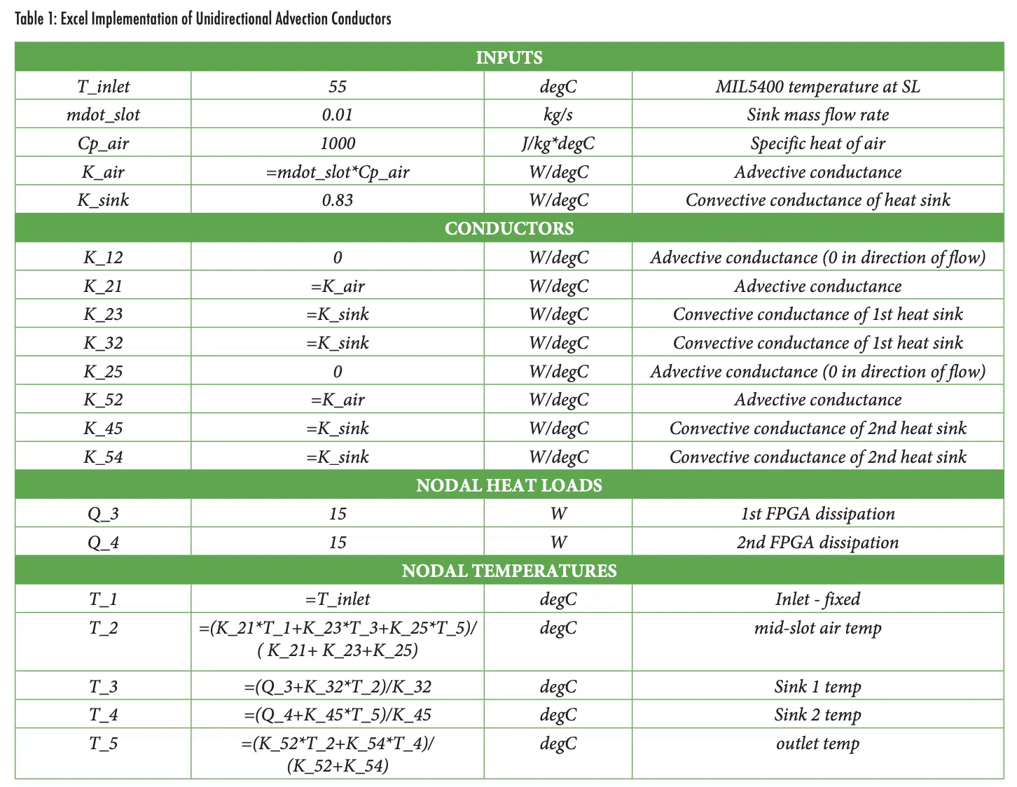
An Excel implementation of the preceding is shown in Table 1 (on the previous page), with formulas instead of values shown. For Excel implementation, iterative calculations must be enabled. Variables do not need to be named fields; this is only done here for clarity.
Discussion
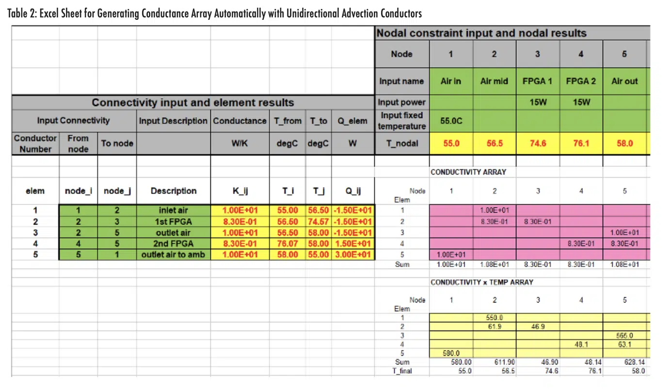
The power of this methodology becomes even more apparent when used in conjunction with more sophisticated array management schemes in Excel, which permit automated assembly of the conductivity array and solution of the thermal network equation for each node. The output area of one such Excel sheet is shown below in Table 2.
The Excel sheet depicted in Table 2 has the capacity for only 20 nodes and 20 conductors, which is sufficient for a typical reduced order thermal network model. The model shown is set up starting with a connectivity array (1) of elements and nodes. A conductivity array is generated by using Excel’s INDEX and IF functions from the conductances (2) taking into account the unidirectional nature of advection elements. The elements of the conductivity array are then multiplied by the nodal temperature array to create a conductivity-temperature array (4). Boundary conditions and loads are input (5). Combining (3), (4), and (5), the thermal network relationship (Equation 2) is formed, and the nodal temperature results generated (6). The advantage of a sheet such as that shown in Table 2 is that it can be made more generic, used for multiple different models, and distributed among multiple analysts for use and refinement.
Note that a matrix-based solution approach, such as that used in [3],[4] does not work correctly with unidirectional advection conductors because the resulting conductance matrix is not symmetric, and therefore not invertible.
Summary
This article described an approach for systematically including advective conductances in a thermal network model. The method allows multiple flow-path segments and heat dissipators. The conductors that account for advection resistance are unidirectional, which prevents the mathematical possibility of heat flowing from the exit of the duct to the entrance of the duct. Since the heat dissipators are linked in the network to the exit node of the duct, the temperatures predicted are higher than that which would be predicted by the Σ-NTU method and are therefore conservative. This method can be implemented in Excel, Mathcad, MATLAB, or any coding package that will allow automated assembly of the conductance array.
References
[1] Ross Wilcoxon, “Advective Thermal Resistance”, Electronics Cooling Magazine, Summer 2022, pp. 6-8
[2] Dave S. Steinberg, “Cooling Techniques for Electronic Equipment”, 2nd Edition, Wiley, 1992
[3] Ross Wilcoxon, “A Spreadsheet Based Matrix Solution for a Thermal Resistance Network: Part 1”, Electronics Cooling Magazine, September, 2010
[4] Ross Wilcoxon, “A Spreadsheet Based Matrix Solution for a Thermal Resistance Network: Part 2”, Electronics Cooling Magazine, June, 2011


