Introduction
A number of years ago I attended a meeting at Purdue University to discuss future challenges and goals for electronics cooling research. One topic that generated a significant amount of interest was, what magnitude of heat flux represented a substantial challenge that the electronics cooling community should be striving to meet with new developments. The closest thing to a consensus that the group could develop was that 1000 W/cm2 seemed like a pretty lofty goal. I had a difficult time agreeing with this, primarily due to the fact that I was helping with the troubleshooting of a production system that had a heat flux of approximately 1200 W/cm2 . The primary factor that allowed us to deal with that magnitude of heat flux was the fact that our component was an LED that dissipated approximately 10W but was less than 1mm2 in size. Clearly, the heat flux alone does not dictate the magnitude of the thermal challenge – the size of the heat source also matters. This becomes obvious with only a little thought; for example, every time we use our cellphone we generate heat flux levels that likely exceed the 10,000 W/cm2 level – but at the micron-sized scale of integrated circuit junctions.
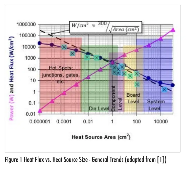
In a paper that described the LED work [1], I spent a little time discussing the heat flux issue and included a chart that showed examples of how the size of a heat source can influence what constitutes a ‘challenging’ heat flux. I collected data presented at a thermal conference to identify heat flux vs. size data and generated a curve fit that provided some guidance on what constitutes a heat flux ‘limit’ for a given heat source area. This is shown in Figure 1. The fact that the data are plotted on a log-log scale gives it stronger appearance of a good correlation than it likely deserves. But it does seem to show a trend of the heat flux limit being roughly proportional to the inverse of the square root of the heat source area. For the data in this plot, the heat source area is the planform area associated with the heat flux; it does not include enhanced area effects such as from heat sink fins.
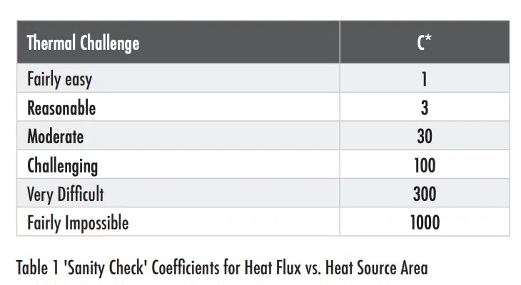
Figure 1 shows that there appears to be a rough relationship between the maximum heat flux (Φlimit) and the size of a heat source (A); namely Φlimit = C*/A1/2, where C* is a constant. The data points shown in the plot were all presented at a conference and appeared to represent challenging, but achievable conditions leading a value of the coefficient C* approximately equal to 300. This is clearly a rough approximation that can be made even more rough by assuming that other levels of technical challenge would also lead to a specific value of C*. With this assumption, we can define values of C* that to correspond to the thermal challenge for a given heat flux and power dissipation in an electronics cooling application. Table 1 shows my attempt at defining values that describe different ‘degrees of difficulty’ for thermal designs.
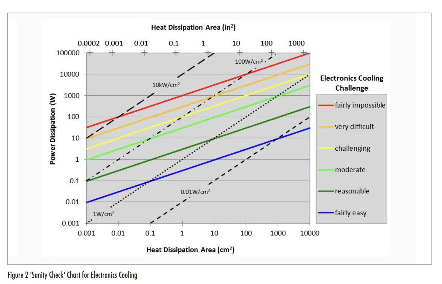
Once values of constants have been defined to describe a level of design challenge, one can then assess the difficulty of thermal management for a given combination of power and area. Figure 2 puts this concept into a graphical form. Based on this chart, a power dissipation of 100 W would be ‘fairly impossible’ for an area smaller than 0.01cm2 , ‘challenging’ for an area of 1cm2 , and ‘reasonable’ for an area of ~1000cm2 .
Before readers cancel their subscriptions to their analysis software and begin basing all future design decisions on Figure 2, they should keep in mind the almost breathtaking number, and extent, of assumptions that went into its generation. The chart extends a very rough regression curve on a limited data set that seems, at best, reasonably representative of electronics cooling applications. But electronics cooling is a relatively broad topic across many industries that have widely varying reliability requirements, ambient temperatures, ambient pressures, types of electronic components, available cooling conditions, types of packaging materials, etc. Figure 2 ignores the effects of these different constraints to develop a broad generalization. Readers should recall the observation of Alexandre Dumas (“All generalizations are dangerous, even this one”) and simply use the figure to develop a sense for how challenging a given thermal condition might be. Better yet, readers may wish to assess their thermal challenges in their own designs, in terms of heat flux and heat transfer area, and use them to define values of C* that correspond to their own experience and create their own version of Table 1. Those coefficients can then be used to produce their own version of Figure 2 that provides a heat flux sanity check that better aligns with their particular design constraints.
REFERENCE
1. Ross Wilcoxon and Dave Cornelius, “Thermal management of an LED light engine for airborne applications”, Twenty-Second Annual IEEE Semiconductor Thermal Measurement And Management Symposium, pp. 178-185, 2006


