ABSTRACT
The small form-factor satellites, CubeSats and SmallSats, have increased in popularity and capability, but advanced thermal solutions are required to keep up with the increasing heat loads. Loop heat pipes (LHPs) are a passive solution capable of transporting heat from electronics to deployable radiator panels. However, due to their complicated structure, LHPs require highly skilled workers and labor-intensive manufacturing process that currently make them cost prohibitive for most small satellite applications. The evaporator and compensation chamber account for almost all of the cost of fabrication, which includes sintering, multiple testing and machining steps, and inserting the knife edge seal. To reduce the fabrication cost of LHPs, a wick fabrication via direct metal laser sintering (DMLS) has been developed. This additive manufacturing process significantly reduces fabrication costs by enabling the construction of the primary wick and envelope in an autonomous single step, while also eliminating the knife-edge seal to offer improved reliability.
This article is written by Advanced Cooling Technologies, Inc., and ACT performed the technical work and cited articles. The article describes a proof of concept LHP primary wick/envelope built via DMLS. A maximum power of 125 W was achieved during steady state testing. Additional tests, including power cycles, adverse elevation, and low power startup, further demonstrate the feasibility of 3D printed LHPs primary wick.
1. LOOP HEAT PIPES
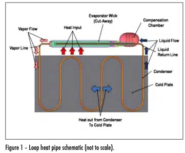
Loop Heat Pipes are passive, two-phase thermal control devices that are used in spacecraft and aircraft thermal control systems. They have been demonstrated to transport up to 1 kW over several meters, in both microgravity and aircraft acceleration. A schematic of an LHP is provided in Figure 1. Heat enters the evaporator and vaporizes the working fluid. The vapor passes through grooves in the primary wick and through the vapor line to the condenser. Here the vapor is condensed and subcooled. The subcooled liquid passes through the bayonet tube into the center of the primary wick. A secondary wick allows for communication between the compensation chamber and center of the primary wick. The compensation chamber contains saturated fluid at a lower pressure than the evaporator, which provides the driving force for fluid flow. The capillary pressure of the primary wick must be greater than the total pressure drop of the system to pump liquid from the liquid line return to the evaporation site at the vapor grooves [1].
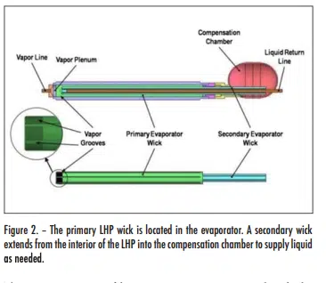
The LHP evaporator wick uses capillary forces to passively supply liquid to the heated surface from the lower pressure condenser. In a heat pipe wick, heat enters from the liquid side of the wick. In contrast, an LHP has an inverted wick, with the vapor located adjacent to the heated surface. LHP wicks are fabricated by sintering metal powder to form a porous body. A typical LHP wick is shown in Figure 2. When the wick is inserted in the evaporator, the outer surface of the wick is in contact with the heated surface. Circumferential and axial grooves are necessary to provide flow channels for the vapor to flow to the vapor line. In this case, the axial and circumferential grooves are machined into the wick, although they can alternatively be machined into the evaporator body.
The evaporator and compensation chamber, shown in Figure 2, have a primary wick in the evaporator, and a secondary wick that extends from the evaporator bore into the compensation chamber. The compensation chamber also has a series of screen wicks running from the secondary wick to the walls (not shown for clarity) that allow liquid to be supplied to the secondary wick in microgravity.
During steady-state operation, liquid from the condenser flows through the liquid return line, which terminates near the end of the bore in the primary wick. The liquid then flows back through grooves in the secondary wick, where it is drawn into the primary wick as needed by capillary forces. During unsteady state operation, the compensation chamber acts like a surge tank. If there is more liquid from the condenser than currently needed, the excess liquid flows through the secondary wick into the compensation chamber. If insufficient liquid is available from the condenser, make-up liquid is drawn from the compensation chamber by capillary forces through the secondary wick, and then the primary wick.
The primary costs to fabricate an LHP are associated with the evaporator and compensation chamber; the remainder is just plumbing [2]. The following steps are required for fabrication: • Machine the evaporator body, and hone the inner diameter (I.D.) to a very precise dimension.
• Sinter the primary wick. Cut off a small test slug, machine, and measure pore size/permeability to verify the wick properties.
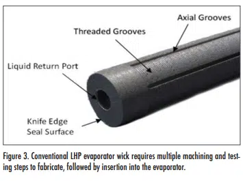
• Machine threaded grooves and axial grooves on the primary wick to remove vapor generated in the evaporator; see Figure 3. The liquid return port is also machined, as well as a flat surface for the knife edge seal. Tight tolerances are required on the outer diameter (O.D.) to allow for an interference fit, and on the flat surface to accept the knife edge seal.
• Measure properties on the as-machined wick. If suitable, insert the wick into the evaporator body with an interference fit.
• Measure pore size and permeability after the wick is inserted.
• Fabricate the secondary wick by sintering screen mesh and then machining grooves. Test the secondary wick [2].
• Insert the knife-edge seal, which prevents high pressure vapor in the evaporator grooves from escaping directly into the compensation chamber. Weld to the evaporator and to the compensation chamber.
• Insert the secondary wick into the primary wick, and verify the performance.
• Assemble the complete compensation chamber. Test in a loop to verify functionality.
LHPs have been used in many large military, research and communication satellites, in which the cost of the LHPs are only a small portion of the overall satellite cost. CubeSats and SmallSats, which are small form-factor satellites, have increased in popularity and capability, but advanced thermal solutions are required to keep up with the increasing heat loads. CubeSats use a standardized modular design and typically have a mass less than 10kg while SmallSats are a family of small satellites with typical mass in the range of 0.1 to 100 kg [3].
Unfortunately, LHPs made by conventional manufacturing methods are too expensive for small CubeSats and SmallSats. The research discussed below is developing a low cost LHP fabrication process via 3D printing to make LHP feasible for small satellites.
2. 3D PRINTING TO REDUCE COSTS
As discussed, conventional LHPs have been widely used in large, expensive, high-powered satellites and aircraft. Over the last decade, CubeSats and SmallSats are used in increasing numbers due to their low cost, short development times, and increases in capabilities in small satellites. Unfortunately, due to the complex fabrication steps discussed above, conventional LHPs are cost prohibitive for these smaller satellites, many of which are built on a very limited budget.
Using a 3D printed wick and evaporator has the potential to lower LHPs costs so that they can be used in smaller, inexpensive satellites. The DMLS fabrication process will eliminate many of the steps discussed in the last section, since the evaporator envelope and primary wick can be fabricated at the same time. The ability to print solid and porous wick material together in a single part also eliminates the need for the conventional knife-edge seal, which improves reliability.
The performance of an LHP primary wick depends largely on pore size. The capillary pressure of a wick is inversely proportional to pore radius. For successful LHP operation, the capillary pressure must be greater than the total system pressure drop. Therefore, by reducing the pore size of the primary wick, the maximum power can be increased. Traditionally sintered primary wicks have a pore radius of approximately 1 µm. DMLS has been demonstrated to be capable of printing porous lattice structures, but the smallest pore size to date has been about 50 µm. This is due to the accuracy and precision of the laser as well as thermal stresses and heat spreading.
In this work, a different approach was taken towards 3D printed wick structures. Instead of building a defined lattice structure, the laser power, speed, and spacing were varied to partially sinter the metal powder together instead of fully melting the particles. This results in a wick structure very similar to that of traditionally sintered wicks.
An experimental optimization study was completed by printing a total of 15 samples using a range of DMLS parameters. The goal was to achieve the smallest possible pore size to maximize capillary pumping power. The pore size was measured for the samples, and varied from 5.6 µm to 32 µm. The smallest pore size is capable of providing enough capillary pressure for an LHP in the 100-300 W range. The DMLS parameters for this sample were used for fabrication of the LHP prototype. Achieving smaller pore sizes is likely possible by using smaller diameter metal powder as the base material, but there are no current commercially available solutions [4].
The LHP evaporator prototype is shown in Figure 4. The vapor vents, shown in the evaporator front (top left), are used to feed the vapor generated in the evaporator to the vapor line. They are formed during the 3D printing process.
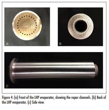
The side of the LHP evaporator is shown at the bottom of the figure, and the back of the LHP evaporator is shown in the top right. One of the main advantages of the 3D printed LHP evaporator is the elimination of the many machining and testing steps needed to insert the primary wick. A second major advantage is the elimination of the knife-edge seal, which seals the pressure difference between the evaporator inverted wick and the compensation chamber. In the 3D printed LHP, the printing parameters were simply altered to provide a solid cap above the wick.
3. EXPERIMENTAL DEMONSTRATION
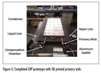
A proof of concept LHP prototype with 3D printed evaporator was built (Figure 5). The working fluid used was ammonia. The primary wick was 2.54 cm in diameter and 10.2 cm in length. The primary wick as printed had a porous interior with a fully dense envelope that was welded directly to the compensation chamber and vapor line. The tubing was 0.318 cm in diameter and the condenser was 99 cm in length. The sink temperature for testing was set to 0°C.
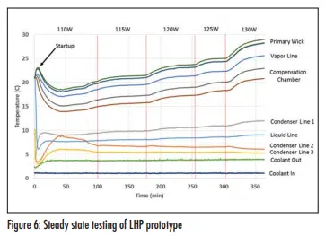
The steady state testing results from the LHP prototype are provided in Figure 6. Startup occurred almost instantly at a power of 110 W, which can be seen by a rapid decrease in the temperature of the liquid line. The power was increased in 5 W increments, and steady state was achieved at a maximum power of 125 W. At 130 W the temperatures of the LHP began to increase linearly which is an indication of dry-out in the primary wick. This power limit can be increased by increasing the length of the evaporator.
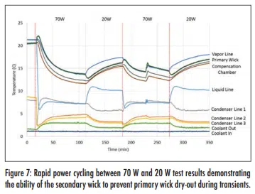
Power cycle testing was completed to verify the ability of the LHP prototype to handle transients. The power was rapidly changed between 70W and 20W. A temperature plot of the results is shown in Figure 7. Dry-out did not occur with rapid increases or decreases in power. This indicates that the secondary wick was able to maintain the supply of liquid to the primary wick during transient operation.
To demonstrate the ability of the LHP to survive launch, the LHP evaporator was subjected to a vibration test representative of launches. Thermal testing after the vibration test showed no change. Additional testing includes low power startup, and testing with the evaporator tilted at a 25º adverse angle to show that the LHP can operate on Lunar and Martian Landers and Rovers. Details can be found in [4] and [5].
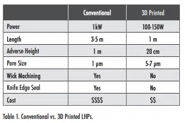
Table 1 compares the properties of conventional versus 3D printed LHPs. The conventional LHPs can carry higher powers over much longer lengths, but are very expensive. 3D printed LHPs can carry less power due to the limitation of current pore size, but still within the range of anticipated CubeSat/SmallSat powers (100 to 150 W). Their greatly reduced fabrication costs make them affordable for these smaller satellites.
CONCLUSIONS
Conventional LHPs are a standard thermal control device for high power military, communication, and research satellites, as well as aircraft thermal control. Unfortunately, they are too expensive for CubeSats and SmallSats, which are increasing in popularity. A newly developed 3D printed LHP evaporator process eliminates many fabrication steps, dropping the fabrication costs to a range suitable for these smaller satellites. An LHP prototype demonstrated the ability of a 3D printed wick to perform as an LHP primary wick. A maximum power of 125 W was achieved which is in the power range of current CubeSat technologies. LHP performance was also verified for operation against gravity and during rapid changes in heat input power. The next step is to verify operation in microgravity as well as further reducing the pore size to increase the power density via smaller diameter metal powder.
ACKNOWLEDGMENTS
This work was funded by NASA through the Small Business Innovation Research (SBIR) program under contract NNX17CM09C. The technical monitor is Dr. Jeffery Farmer. We would like to thank Joel Crawmer and Merryl Augustine for their help in developing the 3D printed LHP. ACT was the recipient of the NASA contract and carried out the reference work.
For more information on ACT, please visit https://www.1-act.com/.
REFERENCES
[1] Ku, Jentung. Operating characteristics of loop heat pipes. No. 1999-01-2007. SAE Technical Paper, 1999.
[2] Anderson, W.G. et al., “Loop Heat Pipe Design, Manufacturing, and Testing – An Industrial Perspective,” ASME 2009 Heat Transfer Summer Conference, San Francisco, CA, July 19-23, 2009.
[3] “What are SmallSats and CubeSats?”, https://www.nasa.gov/ content/what-are-smallsats-and-cubesats, accessed May 10, 2019.
[4] Richard, B. et al., “Development of a 3D Printed Loop Heat Pipe,” Semi-Therm, San Jose, CA, March 18 – 22, 2019.
[5] Richard, B. et al., “Development of a 3D Printed Loop Heat Pipe,” to be presented as the 49th International Conference on Environmental Systems, Boston, MA, July 7-11, 2019.


