INTRODUCTION
Traditionally, medical science has depended on a variety of diagnostic tests administered by medical personnel to either detect the onset of an illness or to monitor its progress. More recently, this focus has been supplemented by a strategy of health maintenance and disease prevention. Both of these strategies benefit from the frequent testing of individuals. Of course, the ideal situation would be continuous sensing of many parameters, highly correlated with the wellbeing of the patient, in a manner that requires no attention or effort on the part of the patient. With the continuing miniaturization of electronic devices, this vision is becoming a reality. There are now devices that are capable of monitoring specific body metrics on a continuous basis. This article explores some of the devices that are providing these functions for us now and also looks at the longer term trends in their development. It also discusses the thermal criteria that are applied to the thermal interaction of such devices with the patient to determine their suitability for use over extended periods of time [1].
EXAMPLES OF ELECTRONIC DEVICES USED IN HEALTHCARE APPLICATIONS
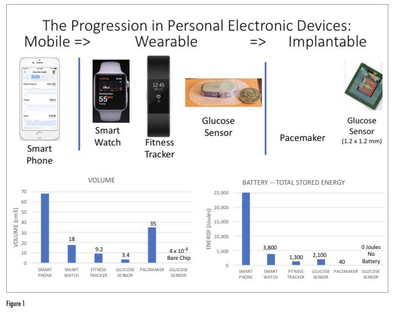
Figure 1 depicts representative examples of mobile, wearable, and implantable devices with a range of capabilities in monitoring and maintaining health. The associated graphs provide a comparison of these devices according to their overall volume and their energy consumption, as represented by the energy storage capability of their battery.
Even though the smart phone doesn’t have the same ability as a wearable device in directly sensing different bodily processes such as pulse, movement, and temperature, it functions as an effective interface to the user in aggregating and processing the results measured by wearable and implantable devices and sharing them with the user as well as with any healthcare provider selected by the user.
The transition from mobile phone, to smart watch, to fitness tracker is accompanied by a similar trend in the reduction in the volume of the device and the energy capacity of their batteries. Both the smart phone and smart watch are multi-purpose devices with advanced computational and communication capabilities, having a high-resolution display. The fitness tracker has a much narrower range of capabilities, a simple display, and only Bluetooth communication capability. This results in a smaller size and much less energy dissipation than the smart watch. All these devices have rechargeable batteries and the expectation is that they will be attached to a charger on a daily basis. Any sensing that they do of the user’s body functions requires only physical contact with the user and no penetration of the user’s skin.
The three devices on the right side of the figure, on the other hand, need to interact with the interior of the user’s body. The glucose sensor needs to penetrate the user’s skin in order perform the glucose measurement. The implantable devices, by definition, are inserted into the user’s body. Both the glucose sensor and the pacemaker employ single-use batteries, that have to be replaced at regular intervals: on the order of months for the glucose sensor and on the order of years for the pacemaker. Hence, the battery capacity for the glucose sensor is larger than that for the fitness tracker, which has more functionality, and therefore higher current draw, but which has the advantage that it can be recharged daily.
The implantable glucose monitor depicted is an experimental prototype and has not yet been commercialized [2]. However, it has features that we can expect to see on other implantable sensors in the future. It is extremely small and can be inserted under the patient’s skin with a simple, out-patient procedure. It has no battery. The approach used here was to use radio frequency waves for both remote monitoring of the sensor using Bluetooth and powering it using wireless power transfer. Both the power transfer and Bluetooth signaling could be provided by a single wearable device, located near the implanted device. Such an implanted device could conceivably perform its functions reliably for years and without any maintenance. In this way, it would require no attention by the user.
VARIETIES OF IMPLANTABLE MEDICAL DEVICES NOW UNDER DEVELOPMENT
The pacemaker is arguably the most widely used implantable medical device at the present time. It differs from the other devices shown here in that it actually controls a bodily function, namely the contractions of the heart. It does not simply monitor it.
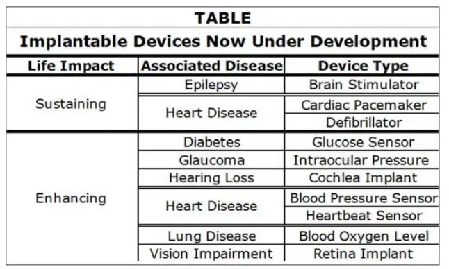
The following table lists implantable devices now in various stages of development [3]. The ones with a life sustaining impact are intended to prevent episodes of either brain or heart irregularities and have a control function. The other devices serve a sensing function, and enhance the quality of life of the patient by ameliorating either vision or hearing impairment or continuously monitoring various vital signs and alerting the user and healthcare providers when an intervention is needed.
They employ wireless communication for data transmission and in most cases use wireless methods of powering the devices.
THERMAL LIMITS FOR PORTABLE AND WEARABLE DEVICES
There are many stationary electronic devices in our homes and offices that we deal with on a daily basis. The thermal engineers involved in their design were concerned mostly with the maximum temperature reached by the various electronic components in the device. Normally, the temperature of the cabinet enclosing a device is at a temperature not much higher than room temperature because the internally-generated heat is typically exhausted from the unit by a flow of air. The people in the vicinity of the device might occasionally touch its exterior, but it would be rare that a person’s skin would be in contact with it for an extended period of time.
With the introduction of mobile and wearable electronics, there are two notable differences:
1) In general, all the heat generated within the device flows via conduction through the outer shell of the device. It is common that the exterior of a mobile device feels warm or even hot to the touch.
2) A mobile device can be in contact with the user’s hand or ear, etc. for an extended period of time. In the case of a wearable device, there could be constant contact with the user’s skin over a period of days.
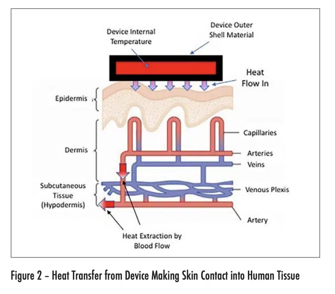
Figure 2 depicts the flow of heat from an electronic device into the outer layer of skin (epidermis) of the user. The maximum temperature experienced by the user is in this layer. The heat is then convectively removed from the heated region by the body-temperature blood flow from the arteries. The heated blood continues into the veins, whence it flows away from the heated region and is dispersed within the body.
Intuitively, we would expect that the probability of getting a burn from skin contact with an electronic device would depend on the following factors: the temperature of the device and the total time the device has been in contact with a particular region of skin. It turns out that the thermal conductivity of the outer shell of the device is also an important factor. Higher conductivity shell materials are associated with more efficient heat transfer to the skin and a higher risk of getting burned at a given combination of device temperature and contact duration.
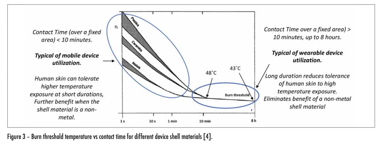
These relationships are quantified in Figure 3, which was extracted from a widely used international standard [4]. The threshold level of severity assumed in this document is that of a second-degree burn.
This graph indicates that, for values of contact time less than a few minutes (typical of mobile device use), human skin can tolerate much higher device temperatures without burning than with longer contact times. Furthermore, as expected, the higher the thermal conductivity of the outer shell of the device, the shorter the time for a burn to occur at a given temperature.
However, for contact times > 10 minutes (typical of wearable devices) a burn can occur at much lower device temperatures (< 48°C) and the use of low-thermal-conductivity materials for the device shell no longer has a mitigating effect. For a contact time of 8 hours, a device temperature of only 43°C can result in a burn.
It is obvious that the mere avoidance of a burn is not enough to achieve a satisfactory user experience. To do this, the user should feel no discomfort at all. An extensive study, involving more than 70 adult subjects, has indicated that the threshold of pain can be avoided by maintaining device temperatures less than 39°C [5].
THERMAL LIMITS FOR IMPLANTABLE DEVICES
The process for determining whether an implantable device is within safety limits is a much more complicated process than that for portable and wearable devices.
To begin with, the role of thermal simulation is critical to perform an initial assessment of the viability of a given device embedded in a particular part of the human body. The simulations are supplemented by tests with animals and by in vivo testing in humans. As referred to in the discussion of the implantable glucose monitoring chip, the deployment of such a chip is greatly simplified if both the communication with the device and powering it up is done wirelessly. However, the fact that these electromagnetic waves are being transmitted through the body, results in the inductive heating of human tissue along the path of these E-M waves.
Hence, there are three sources of heat to be accounted for:
• Conductive heat transfer from the embedded device into the surrounding tissue
• Inductive heating of tissue along the path of the E-M waves
• Metabolic heat generation in a specific volume of tissue.
Additionally, there is a cooling mechanism due to the flow of blood through a volume of tissue referred to as perfusion.
The combined effect of these heating and cooling processes has to be accounted for in using the appropriate simulation methodologies. Once the temperature distribution throughout the portion of the body of interest is calculated, the results can be compared with various criteria, depending on the part of the body being affected.
The literature indicates that the following are acceptable limits are for most tissues in the body [6]:
• 2°C increase in the temperature of the affected tissue
• 40 mW/cm2 heat flux flowing from the surface of the device into the surrounding tissue
• 1.6 mW/g of heating caused by the transmission of the E-M waves through the tissue of interest.
• The standards documents, referred to this quantity as SAR (Specific Absorption Rate) [7].
-One exception is in the brain:
• Very little is known about human cerebral tissue’s response and tolerance to chronic exposure to a thermal stress from an implantable that generates low (<2°C) temperature changes [8].
THERMAL MODEL FOR THE TRANSFER OF IN THE HUMAN BODY
The Pennes bioheat equation is considered to be the standard in the field [6]. It was developed in 1948 by Harry H. Pennes. Because of the extensive use of this model, the required material properties have been measured for nearly all tissue types in the human body as well as for certain animals. It is essentially a time-dependent conduction model accounting for the three heating mechanisms just mentioned as well as the cooling effect of perfusion. However, its utility in many situations results from the wealth of material properties relevant to most of the types of tissue in the human body and in certain animals as well.
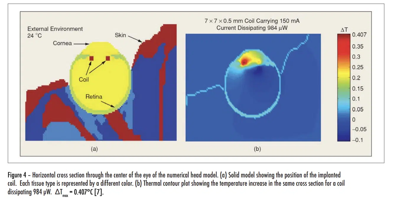
The Pennes equation is not discussed in detail here. However, some insight into the methodology can be gained to looking at thermal simulation results based on the method depicted in Figure 4.
The figure shows only part of a model of the entire head, with a retinal prosthesis mounted in the left eye, whose function is to partially restore sight in a visually impaired person. In the front of the prosthesis, there is an area-array photo sensor that communicates wirelessly with a retinal stimulating chip using a telemetry coil. This chip stimulates the retina by way of a microelectrode array attached to it. It should be noted that the model of the entire head includes 22 distinct types of tissue, each with its own thermal properties, metabolic rate, perfusion rate, etc. The E-M waves emitted by the telemetry coil heat up the surrounding tissue. The model calculates a maximum temperature increase of 0.41°C, which is within the allowable limit [9].
CONCLUSIONS
In the past 10 years, there have been significant advances in mobile and wearable devices. They are widely used in healthcare monitoring and fitness tracking. While there have been developments in implantable devices, they are still at the preliminary stages. However, they have the greatest potential to revolutionize healthcare by offering an always-on, web-enabled monitoring capability. Thermal characterization of these devices in an in vivo environment offers many challenges. Fortunately, they are being met by the rapid development of the necessary thermal tools.
REFERENCES
[1] B. Guenin, “Wearable Electronics in Healthcare: Technology, Applications, and Challenges,” Presented in panel session P2: Thermo-fluidic Challenges in Healthcare. iTherm Conference, 2018, San Diego
[2] Report, World Health Organization (WHO) – “Global Report on Diabetes,” 2016
[3] J Walk, et al., “Remote Powered Medical Implants for Telemonitoring,” Proceedings, IEEE, Vol. 102, No. 11, Nov. 2014
[4] IEC GUIDE 117 — Electrotechnical equipment – Temperatures of touchable hot surfaces Appendix A, 2010.
[5] R. Defrin,1 A. Ohry, N. Blumen, and G. Urca, “Sensory determinants of thermal pain,” Brain (2002), 125, 501-510
[6] Patrick D. Wolf, “Thermal Considerations for the Design of an Implanted Cortical Brain–Machine Interface (BMI),” Chapter 3 in, “Indwelling Neural Implants: Strategies for Contending with the In Vivo Environment,” W. M. Reichert WM, editor, CRC Press, 2008. Available online at: https://www.ncbi.nlm. nih.gov/books/NBK3932/
[7] IEEE Standard for Safety Levels with Respect to Human Exposure to Radio Frequency Electromagnetic Fields, 3 kHz to 300 GHz, IEEE Standard C95.1, 1999.
[8] Huan Wang et al.,”Brain temperature and its fundamental properties: a review for clinical neuroscientists,” Frontiers in Neuroscience, Vol. 8, p 307 (2014).
[9] G Lazzi, “Thermal Effects of Bioimplants — Power Dissipation Characteristics and Computational Methods, “IEEE Engineering In Medicine And Biology Magazine, Sept./Oct. 2005.
