Introduction
Industry power trends and a global push for sustainability are leading decision-makers and data center operations groups to consider alternatives to traditional air cooling. Two key industry trends are driving alternative cooling solutions.
First, powers at the chip level are increasing [1,2]. Just a couple of years ago, server CPU and GPU power levels were only 205 W and 300 W, respectively. Today, performance competition among CPU vendors is pushing power towards 500 W. Artificial intelligence and machine learning workloads have pushed GPU power to 700 W with 1000 W likely just around the corner. Increased CPU and GPU power impacts the temperatures at which these components can operate. The silicon that makes up these parts is temperature-limited. Because of the silicon limits, the junction temperature can be considered fixed. When more power is pushed through the processor package, the case temperature must come down to keep the junction temperature the same to maintain operationally. On the one hand, the powers are increasing higher and higher, while on the other, the CPUs and GPUs must be cooled to lower and lower temperatures [1,3]. This stresses the traditional air-cooling approach, which is leading to the consideration of new liquid cooling solutions [4,5,6,7]. In addition to the power and temperature trends, the global energy crisis is pushing all sectors to be more sustainable. For servers and data centers, this sustainability push means operators are targeting green energy sources, overall reductions in facility energy use, and the reduction or elimination of water use. These industry challenges require new cooling solutions to both enable sufficient cooling at power levels beyond the capability of air cooling and to yield solutions that offer realizable sustainability opportunities. Five unique cooling solutions exist in the market today; each have varying cooling performance, cost, and reliance on facility chilled water supplies. These technologies include: air cooling using larger server chassis form factors, direct liquid cooling (DLC) using water or Propylene Glycol (PG) solutions, DLC using two-phase dielectric fluids, single phase immersion, and two-phase immersion. The thermal performance of these technologies was com- pared using simplified, algebraic thermal models. The full work has been published in the IEEE Proceedings of SEMI-THERM 39 [8]. This work focuses on the thermal solution alone, which is only one of the factors considered when selecting a cooling technology. In picking a cooling solution, one should also consider the relative cost, complexity, serviceability, and environmental impact of each technology in addition to data center facilities and the relative thermal performance of the cooling solutions.
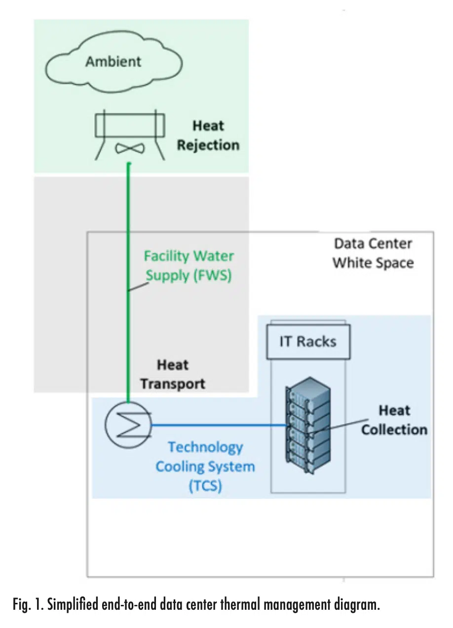
Figure 1 shows a simplified data center and its end-to-end thermal management system. The system was broken down into three components: heat collection (blue), heat transport (grey), and heat rejection (green). In the heat collection portion, the cooling technology captures the heat from the IT gear. For trans- port, the heat is carried from the technology cooling system to the heat rejection system. Lastly, the heat rejection segment generates relatively cool facility water by rejecting the heat to the local environment. If an air-cooled system is taken as an example, then heat collection occurs as the air blows past finned heat sinks and circulates to the air handler. Facility water then removes the heat from the air and the heat is rejected to the ambient environment.
Unique cooling solutions in the market each have different performance, cost, and facility water requirements. Six configurations were represented as simplified thermal models for this comparison:
- Air-cooling in a 1U configuration
- Air-cooling in a 2U configuration
- Single-phase DLC (1-2 liters per minute, lpm)
- Two-phase DLC
- Single-phase immersion
- Two-phase immersion
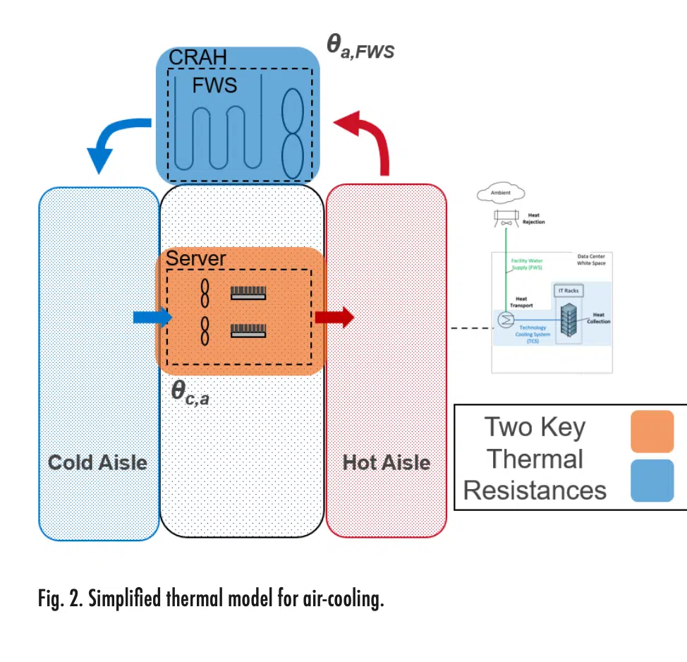
Figure 2 represents the simplified thermal model for air-cooled servers. The heat collection portion of the end-to-end system was broken down into two primary thermal resistances: one at the server level (orange) and another at the facility level (blue). The server level captures the resistance between the chip case and the air (θc,a), while the facility level, i.e. computer room air handler (CRAH) represents the resistance between the air and the facility water (θa,FWS). The resistance at the server lev- el was modeled from experimental data and the resistance on the facility side was gathered from manufacturers’ data. Both air-cooled configurations (1U and 2U) are represented by Figure 2. The primary difference in the model for these configurations is the heat sink resistance value, which can be viewed in Reference 8. Furthermore, Reference 8 provides simplified thermal models and corresponding resistance values for the remaining cooling technologies, including immersion and DLC.
When reviewing the results of the thermal modeling, it is important to keep in mind the following about the thermal resistances used:
1) These values represent typical server thermal resistances for an Intel Sapphire Rapids Thermal Test Vehicle (TTV) used ac- cording to Intel’s specifications. Data for the same TTV design was used for all of the thermal technologies, allowing for an apples-to-apples comparison.
2) The heat sinks, cold plates, etc. tested were typical for the generation of servers launched in early 2023. There are devices across the technologies that can achieve higher performance. There may be higher performing TIM materials. However, the intent was to compare devices that are deployed at scale, or could be deployed at scale, and thus considerations must be made for quality, reliability and scalability of the thermal technology devices.
3) Even with the above considerations, data center servers have wide-ranging designs and no two deployments are identical. This study intentionally ignored important behaviors like pre-heating of coolant from other components in the server so that we could focus on a direct comparison of the thermal technologies in a truly one-to-one manner. Actual thermal resistance performance in the field can be expected to vary by up to 20% for a given thermal technology.
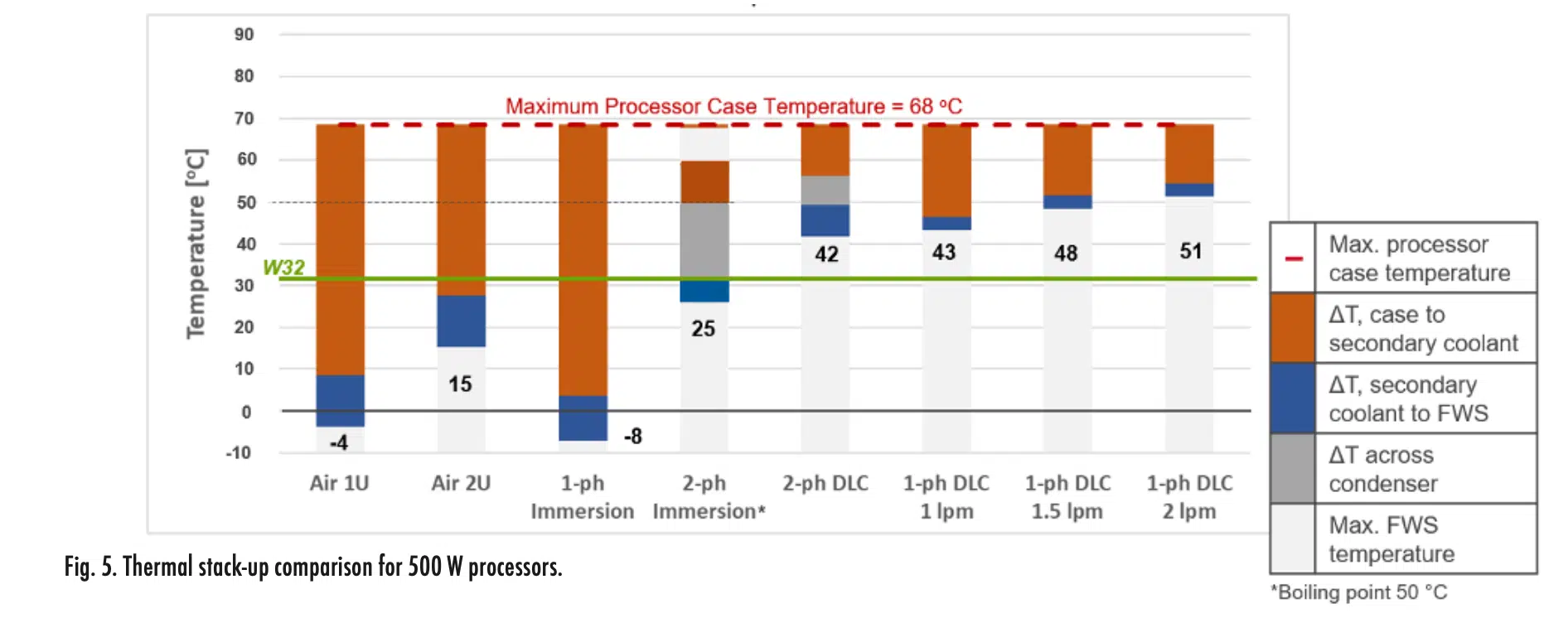
4) The temperatures shown in Figures 4 and 5 should be used only to compare technologies and not as design recommendations. Again, this study intentionally simplified the cooling systems so that the performance of different cooling technologies could be compared. The actual cooling water temperatures will certainly vary depending on the exact deployment. Keep in mind that in most cases, the cooling water temperatures shown will tend to be optimistic, i.e., higher, compared with actual data center deployments.
5) The authors are aware of improvements being made in the areas of air-cooled heat sinks and closed loop Liquid Assisted Air Cooled (LAAC) systems since the testing for this study was performed. Single-phase immersion systems are expected to improve similarly. While this will extend the range of processors that these technologies can cool, these improvements do not significantly impact the conclusions of the relative performance of the technologies, nor the general trend toward the need for liquid cooling as processor TDPs increase. Nor do we see indications that single phase immersion thermal resistances will vary significantly from air-cooled heat sink thermal resistances.
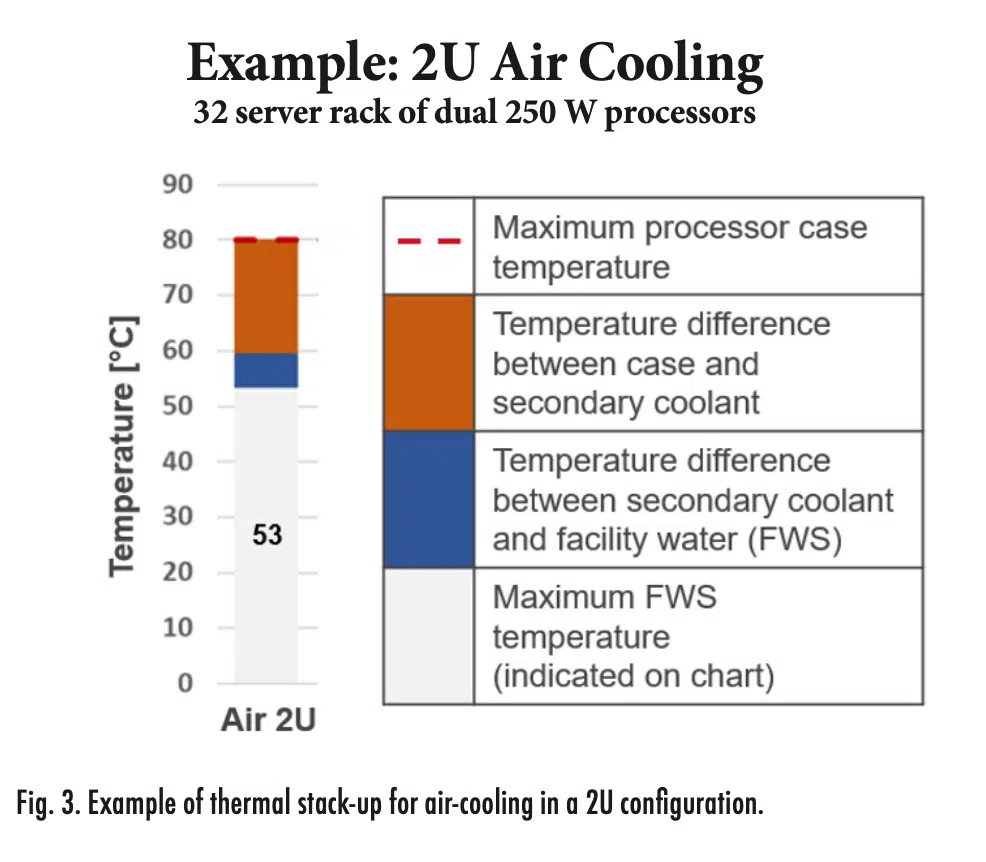
We can visualize how the thermal resistance affects the maximum theoretical facility water (FWS) temperature for each of the technologies with a thermal stack-up chart. Figure 3 shows an example of the thermal stack-up for air-cooling in a 2U configuration; this includes a 32-server rack with dual 250W processors. For 250W processors, we assume a maximum processor case temperature of 80°C, as indicated by the red dashed line. The orange bar represents the temperature difference due to the server level thermal resistance between the processor case and the air (θc,a). In this example, the case-to-air resistance leads to a temperature difference of about 20°C. The blue bar represents the temperature difference due to the facility side resistance (θa,FWS), which is approximately 7°C. Taking the total temperature difference between the case and the facility water (27°C), and subtracting that from the maximum processor case temperature (80°C), gives the maximum allowable FWS temperature of 53°C.
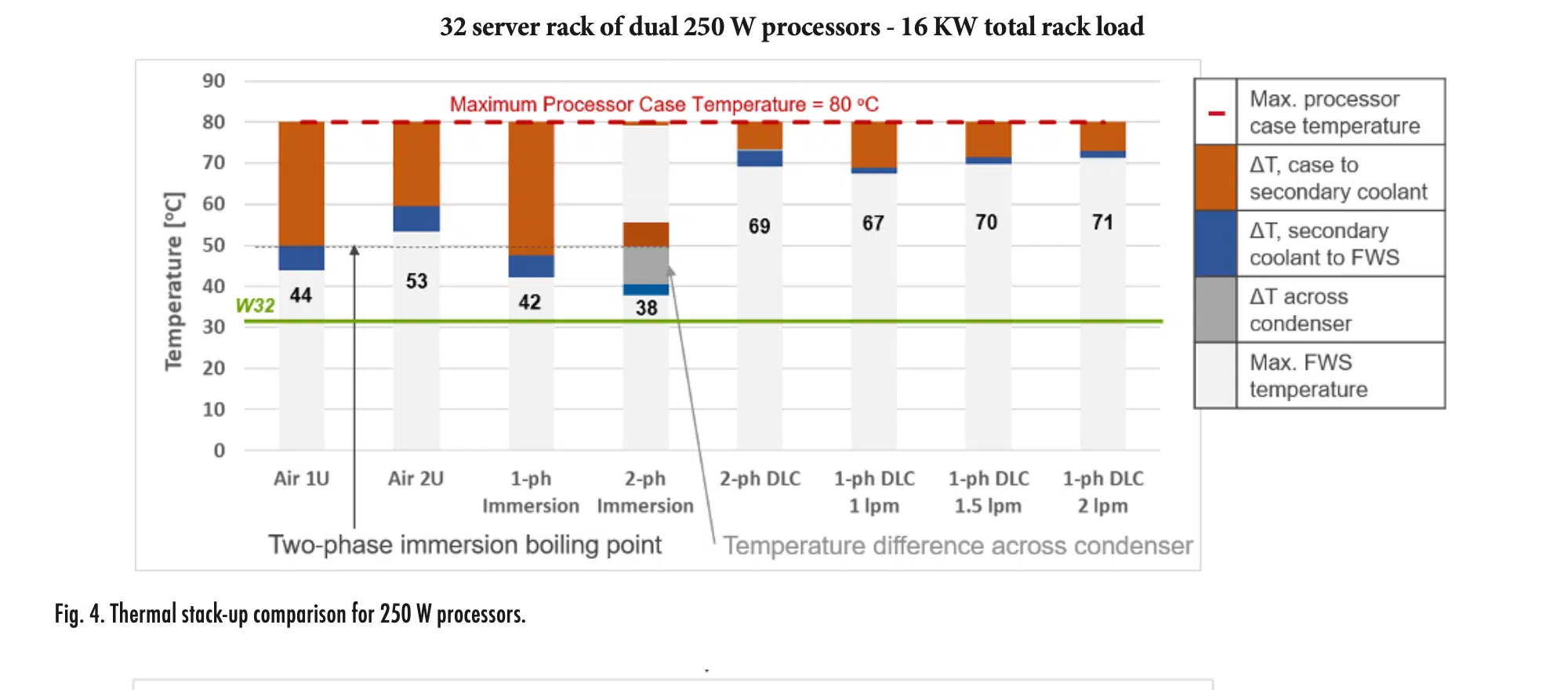
Figure 4 shows the thermal stack-up for all technologies considered with 250W processors. The maximum FWS temperature for each technology can be compared against the W32 line in green on the chart. W32 is a liquid cooling class from the ASHRAE equipment environment specifications for liquid cooling, and it corresponds to 32°C facility water [9]. W32 is a useful reference because, in many climates, facility water can be maintained at this temperature with minimal use of compressors. Each technology has a reference point relating to the maximum processor case temperature except for two-phase immersion. Because two-phase immersion includes boiling at atmospheric pressure, the reference point for that technology must be the boiling point for the fluid, which is taken to be 50°C. For 250W processors, all the technologies investigated allow for FWS temperatures above 32°C. Two-phase immersion requires the lowest theoretical FWS temperature at 38°C. This is followed by air in a 1U configuration and single-phase immersion, which have similar maximum FWS temperatures. Air in a 2U configuration allows for slightly higher temperatures on the facility side, and single-phase and two-phase DLC allow for much higher FWS temperatures at this power level.
Figure 5 shows the impact of increasing the processor power to 500 W. For this power level, the maximum processor case temperature is reduced to 68°C, which is an estimate for future processors at this operating point. There is a notable difference in the maximum FWS temperatures. Air cooling in a 1U configuration and single-phase immersion are the most challenged by this higher power; their resistances lead to negative facility water temperature requirements. Furthermore, air in a 2U configuration and two-phase immersion both require FWS temperatures below W32. In contrast, single-phase and two-phase DLC still allow for FWS temperatures greater than W32 with plenty of headroom. Lastly, as the power increases from 250W to 500W per processor, the impact of the thermal resistance across the condenser for two- phase immersion and DLC greatly increases.
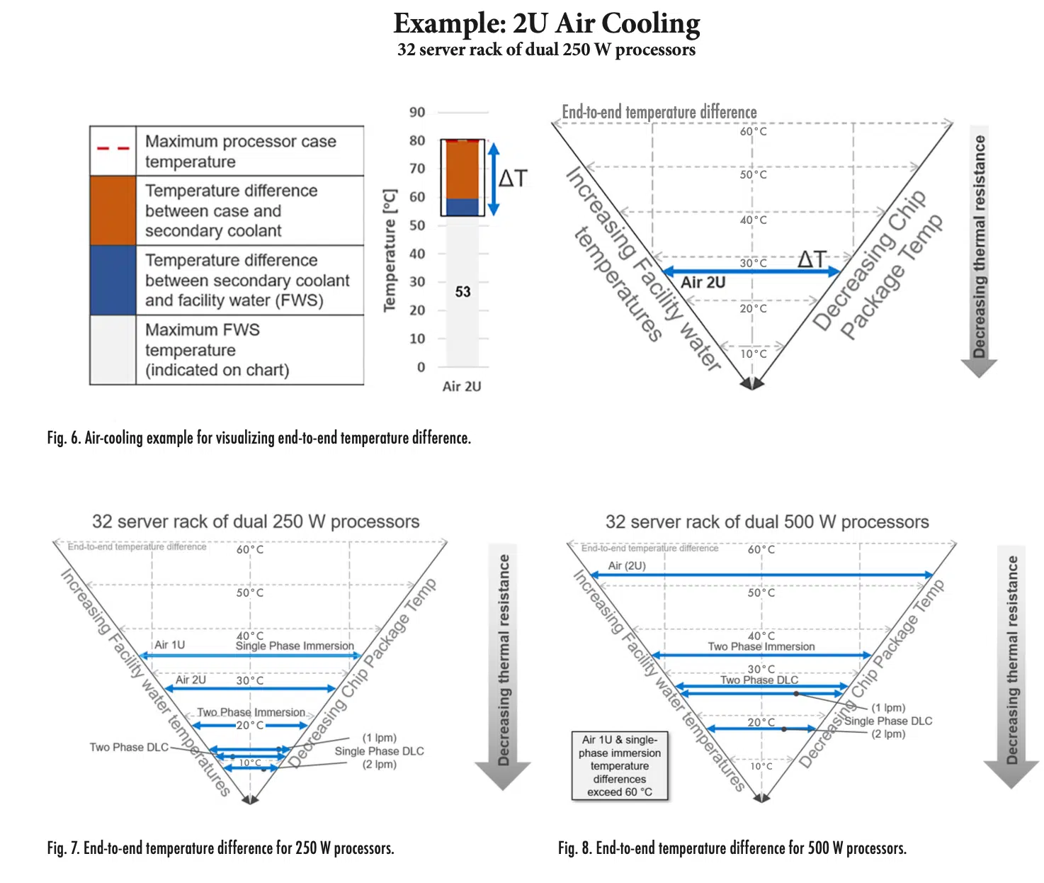
The end-to-end temperature difference between the chip case and the facility water can also be visualized in a V-plot. Figure 6 shows an example of the connection between the stack-up plots and the V-plots for air cooling in a 2U configuration. A box is drawn around the end-to-end temperature difference on the stack-up, as indicated by the blue arrow. This arrow is then added to the V-plot on the right. The left-hand guide represents increasing fa- cility water temperatures, while the right-hand guide represents decreasing chip package temperatures. The end-to-end temperature difference is shown within the V created by these two guides. For this visualization, the thermal resistance decreases from top to bottom. A technology with a lower thermal resistance will be at the bottom of the chart, and a higher resistance will sit at the top.
Figure 7 shows the end-to-end temperature difference for all the technologies for 250W processors. Air cooling for a 1U configuration and single-phase immersion have similar thermal performances and have the highest thermal resistances. Single-phase and two-phase DLC are at the bottom of the chart with the lowest thermal resistances. Two-phase immersion and air cooling in a 2U configuration fall in the middle.
Figure 8 shows the comparison when the power is increased to 500W. There is a wider range in the end-to-end temperature difference, as shown by the increased spacing. Notably, because air cooling for a 1U configuration and single-phase immersion had temperature differences greater than 60°C, they are not shown on the plot. Single-phase DLC exhibits the lowest temperature difference and thus, the lowest thermal resistance. Two-phase DLC is close to single-phase DLC with 1 lpm, and two-phase immersion follows. Air cooling in a 2U configuration has a large temperature difference, indicating thermal challenges at this power.
In comparing the thermal performance of different technologies, we see that air cooling and immersion cooling are challenged by high powers approaching 500 W and beyond. These limits may be pushed further by advances in heat sinks and air movers or circulators for air cooling and immersion, respectively. The limits could also be pushed further by larger processor footprints, which would spread the heat flux over a wider area. It should be noted that air cooling is often limited by the impact of the processor heat on the other components in the system. This impact was not included in the simplified thermal models, but it should be considered in a system design. The limiting factors for two-phase immersion are the fluid boiling points and the condenser performance. Single-phase and two-phase DLC were shown capable of cooling up to 500W processors with available thermal margin to W32 facility water. A limiting factor for two-phase DLC is the flow resistance of the vapor return path; this should be addressed in future design iterations. Advances in designs or fluids may improve two-phase DLC performance. Single-phase DLC was shown to have the best thermal performance of the technologies investigated with a potential to cool at least 1500W processors.
It is important to stress that this work focuses purely on the thermal performance of these different cooling technologies as they stand today, and it does not consider other important aspects in the selection of a cooling strategy such as relative cost, complexity, serviceability, and environmental impact of each technology. Based on this thermal performance analysis, while innovations are expected in each of the technologies, it appears that DLC will require the fewest technical improvements to meet future cooling needs.
Acknowledgments
It is to note that Dr. Emily Clark is a Thermal Technologist in the Chief Technology Office at Dell Technologies. She focuses on thermal solutions and innovations for server and data center cooling. Emily completed her PhD as a Bredesen Center Fellow at the University of Tennessee. She performed her doctoral research at Oak Ridge National Laboratory, which focused on cooling of plasma-facing components in nuclear fusion reactors. She previously worked at Raytheon Technologies, where she focused on cooling complex systems. With her experience and research, Dr. Clark assisted in the execution of publishing this article.
References
[1] Intel Product Specifications, Intel Corporation, 2023, https://ark.intel.com/. Accessed 12 Jan. 2023.
[2] AMD Product Resource Center, Advanced Micro Devices, Inc.,2023, https://www.amd.com/en/products/specifications/. Accessed12 Jan. 2023.
[3] “Thermal Design Guide for Socket SP3 Processors,” AMD Tech Docs, Advanced Micro Devices, Inc., Publication number 55423,Rev. 3, Nov. 2017. Accessed Online. 2023, https://www.amd.com/en/support/tech-docs. Accessed 12 Jan. 2023.
[4] Kheirabadi, A. C., Groulx, D., “Cooling of server electronics: A design review of existing technology,” Applied Thermal Engineering, Vol. 105, pp. 622-638, 2016[5] W. Zhao, S. Wasala and T. Persoons, “Towards quieter air-cooling systems: Rotor self-noise prediction for axial cooling fans,” in 28th International Workshop on Thermal Investigations of ICs and Systems (THERMINIC). IEEE, Sep 2022, pp. 1–4. [Online]. Available: https://ieeexplore.ieee.org/document/9950669/
[5] Shahi, P., et al., “CFD analysis on liquid cooled cold plate using copper nanoparticles,” ASME 2020 International Technical Conference and Exhibition on Packaging and Integration of Electronic and Photonic Microsystems, Virtual, 27-29 Oct., 2020. [6] Shahi, P., Saini, S., Bansode, P., Agonafer, D., “A comparative study of energy savings in a liquid-cooled server by dynamic control of coolant flow rate at server level,” IEEE Transactions on Components, Packaging and Manufacturing Technology, Vol. 11, No. 4, pp. 616-624, 2021.
[7] Fan, Y., Winkel, C., Kulkarni, D., Tian, W., “Analytical design methodology for liquid based cooling solution for high TDP CPUs,” 2018 17th IEEE Intersociety Conference on Thermal and Thermomechanical Phenomena in Electronic Systems (ITherm), 2018, pp. 582-586, doi: 10.1109/ITHERM.2018.8419562.
[8] Curtis, R., Shedd, T., and Clark, E.B., “Performance Comparison of Five Data Center Server Thermal Management Technologies,” 2023 39th Semiconductor Thermal Measurement, Modeling & Management Symposium (SEMI-THERM), San Jose, CA, USA, 2023. [9] 2021 Equipment Thermal Guidelines for Data Processing Environments: ASHRAE TC 9.9 Reference Card, ASHRAE, From Thermal Guidelines for Data Processing Environments, Fifth Ed., 2021.

