Introduction
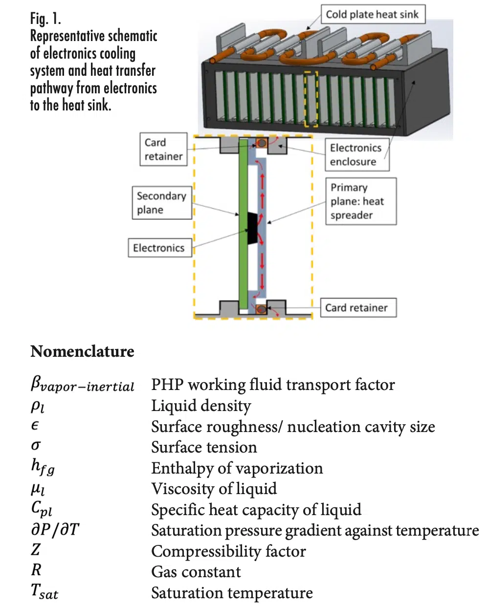
Modern electronics are rapidly evolving to meet high-computing needs while shrinking in size resulting in large heat fluxes that must be removed for safe operation. Figure 1 shows a schematic of a generic electronics cooling system with representative heat transfer pathway from a chip (heat source) to a cold plate (heat sink) via heat spreaders and card retainers (e.g., Wedge-loks).
Heat spreaders are the first thermal link that remove heat from the electronic chips directly and transfer it to a chassis via mechanical card retainers, which expand in one-direction, that are commonly called wedge-loks. The heat is further dissipated from the chassis to an enclosure heat sink (shown in Figure 1 is a cold plate-based heat sink). Conventional cooling systems with aluminum plate-spreaders with limited thermal conductivity (k≈180 W/m-K) and conventional wedge-loks are incapable of maintaining electronics temperature below 70°C at high heat fluxes. To address this challenge, it is necessary to explore alternative cooling solutions for the next generation of high-performance computing systems. Two-phase heat spreaders, such as Embedded Heat Pipe (EHP) and Pulsating Heat Pipe (PHP) plates, along with thermally enhanced wedge-loks that expand diagonally (i.e., two directions) are alternative high-performance options. This article will first discuss each of these components and provide general (design) guidelines. Subsequently, a study comparing an advanced electronics cooling system with two-phase heat spreaders and enhanced wedge-loks against the current state-of-the-art system is presented.
Advanced Passive Electronics Heat Spreader Technologies
Embedded Heat Pipe (EHP) Heat Spreader
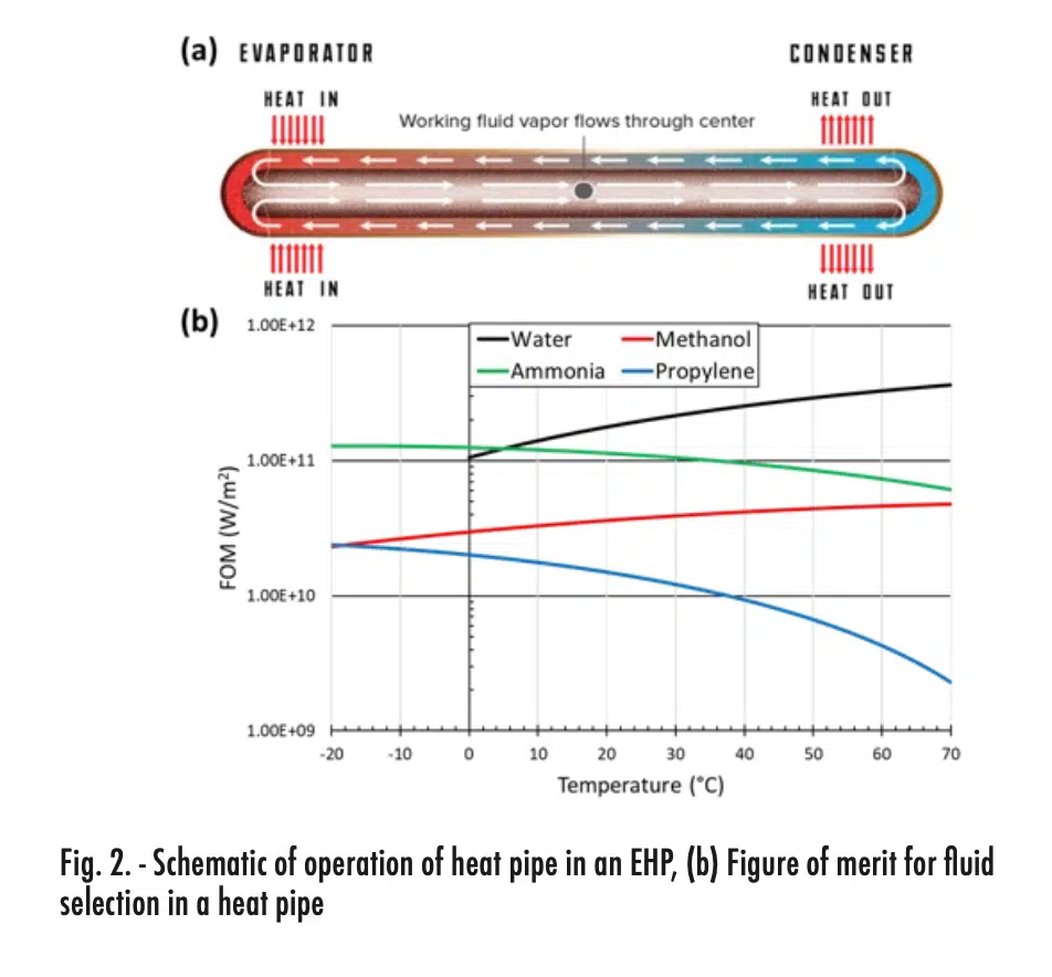
An EHP heat spreader is comprised of heat pipes embedded in an aluminum baseplate, to result in a high conductivity plate [1]. Figure 2 (a) shows the schematic of operation of the heat pipe. A heat pipe is a device that utilizes evaporation and condensation of a working fluid inside a sealed container for heat delivery: Heat applied on one end (evaporator side) is transported to the other end by the vapor resulting from phase transition of the working fluid. The vapor condenses at the other end (i.e., condenser side) and the condensation returns to the evaporator by capillary forces. Further details on the heat pipe operation can be accessed in [2]. Typically for an EHP plate, heat pipes made of copper tube are used with a compatible working fluid. The working fluid is selected based on the Figure of Merit (FOM), which is a fluid property derivative from the capillary limit [3]:
Figure 2 (b) shows the FOM of various fluids for heat pipes. Generally, electronics operate in the range of -20°C to 70°C. In this operating temperature range, water is the best heat pipe working fluid, followed by ammonia. Water is also compatible with copper, so Cu-H2O heat pipe is a common choice for EHP in electronics cooling applications. A tool that can help a designer to determine appropriate heat pipe size and wick structure is available in [4].
Pulsating Heat Pipe (PHP) Heat Spreader
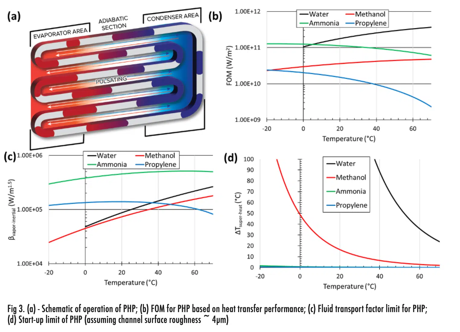
Compared to a heat pipe, a PHP is an emerging passive heat transfer device. Instead of using a wick to return liquid, a PHP uses pulsations (or oscillations) of the working fluid inside a meandering capillary-sized channel connected end to end, as shown in Figure 3 (a), to transport thermal energy. A distinct requirement of the PHP is that the serpentine channel diameter must be smaller than the critical diameter, dictated by the Bond number limit (<4), so that the working fluid inside the channel naturally distributes into liquid slugs and vapor plugs. Heat applied to one end is transported to the other end utilizing fluid pulsations/ oscillations of liquid slug-vapor plug pairs. Further details on the operation of PHP can be accessed in [5].
The selection of a PHP working fluid should consider multiple factors, including Figure of Merit (FOM), fluid transport factor (βvapor-inertial) and minimum superheat for start-up (ΔTsuper-heat). The FOM for PHP working fluid selection is based on the thermal performance of a PHP based on fluid properties, as discussed in work of Kim et. al. [6]:
Figure 3 (b) shows the performance-based FOM for various PHP working fluids. Ammonia appears to be the best working fluid, closely followed by propylene. Water and alcohols are less suitable as they require high superheat compared to refrigerants. In addition to high heat transfer performance, the selected working fluid should also enable a PHP to handle higher heat fluxes and have an easier start-up. The maximum heat transfer capability, also called the transport factor (βvapor-inertial), can be estimated by the following equation presented in [7]:
The minimum superheat required for PHP start-up based on nucleate boiling is estimated using [8]:
In summary, it is desirable to select a working fluid for PHPs with a higher FOM and transport factor while requiring a lower superheat to startup. Figure 3 (c) shows βvapor-inertial for PHP working fluids, where it is evident that ammonia is the best working fluid within the operating temperature range of -20°C to 70°C. This is followed by propylene, which has a decreasing trend after 40°C.
Figure 3 (d) shows the superheat requirement for the start-up of the PHP. The curves show water and alcohols have significant superheat requirements while refrigerants are more favorable for faster start-up. From a thermal performance perspective, ammonia should be considered as the most suitable working fluid within this operating temperature range. Propylene is the second-best option. Other factors such as safety, structural, compatibility also need to be considered, depending on different operational scenarios. For example, the PHP prototypes developed, tested and discussed in the remaining sections were charged propylene due to safety considerations.
Thermal Performance Comparison of EHP and PHP Heat Spreaders
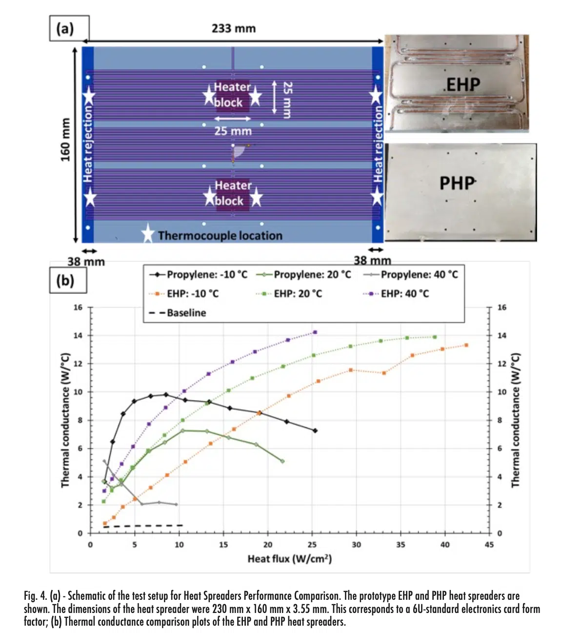
Figure 4 (a) shows the heat spreaders tested, which had two center heaters (red section) with edge condensers (blue section). A quasi-steady state testing method was adopted with incremental heater power. The size of the heat spreaders was 233 mm x 160 mm x 3.55 mm. Further details on the heat spreaders can be found in [9]. The thermal conductance was calculated as [9]:
Where, Q is heater power, and ΔT is average temperature difference between evaporator and condenser temperature.
Figure 4 (b) shows the thermal conductance (C) of the heat spreaders at different coolant circulation temperatures. The black dashed line represents the baseline (empty PHP) thermal conductance of 0.5 W/°C. The thermal conductance of the PHP is represented by solid lines with markers and the thermal conductance of the EHP is represented by dotted lines with markers. At low temperature, the PHP with propylene showed higher thermal conductance compared to the EHP, up to a heat flux of 19 W/cm2. The maximum PHP thermal conductance recorded was > 9 W/°C (18 times more than the baseline). At higher heat flux, the PHP operated in partial dry-out mode with decreasing thermal conductance, while that of the EHP increased up to 13.3 W°C with a heat flux of 42.4 W/cm2. The propylene PHP had better or similar performance compared to EHP at lower heat fluxes and at lower set point temperature. Otherwise, the EHP showed superior thermal performance as a heat spreader.
Enhanced Card Retainer (ICE-Lok) for Improved Junction Thermal Conductance
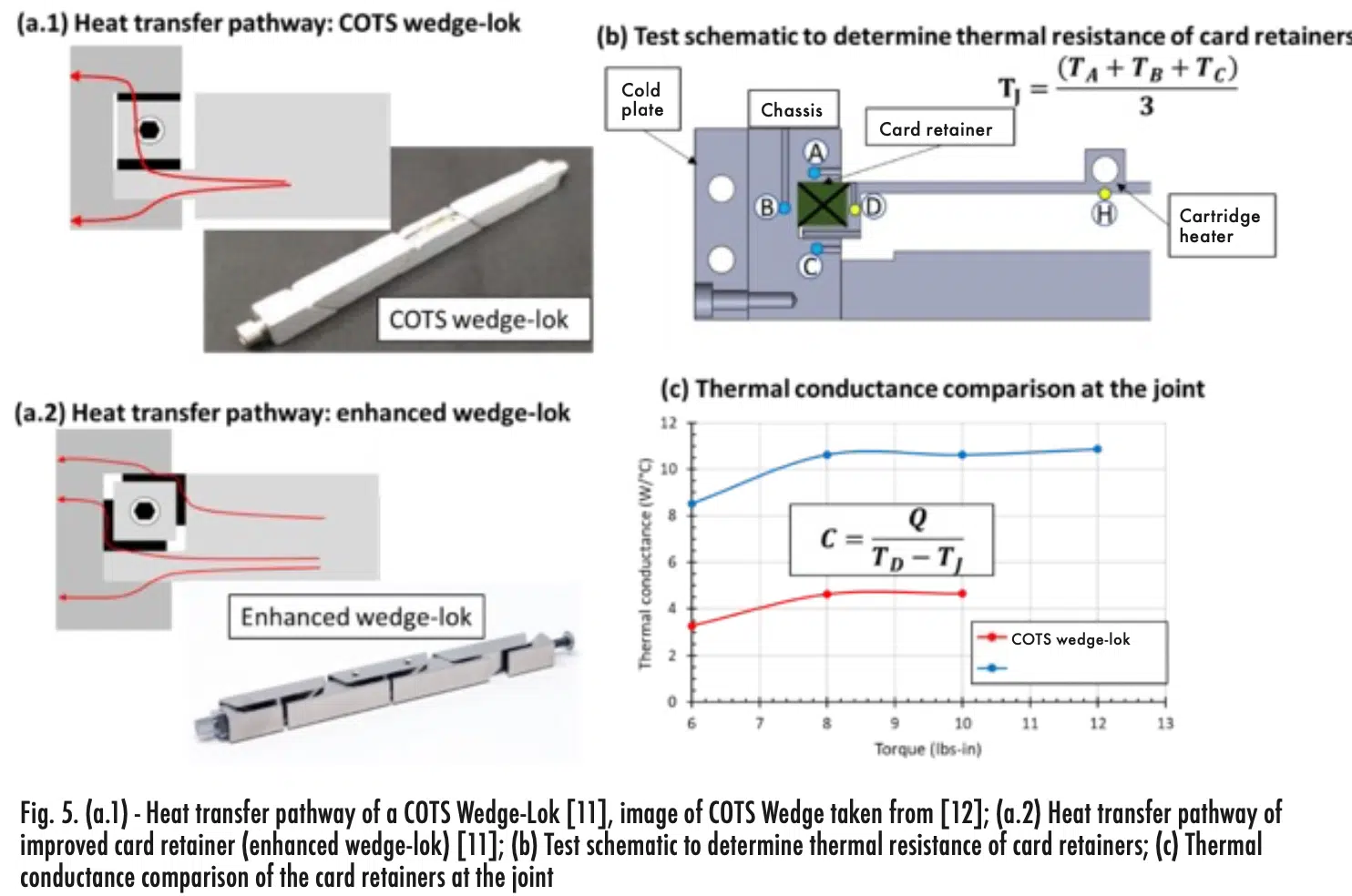
The heat spreader is connected to the electronics chassis by a card retainer (i.e., wedge-lok). As the torque applied to the retainer in- creases, the wedges expand and make contact with chassis slots to provide a heat transfer pathway between the surfaces. Figure 5 (a.1) shows the heat transfer pathway in a commercial-Off-The-Shelf (COTS) wedge-lok. An improvement over a COTS wedge-lok is an enhanced wedge-lok, or ICE-Lok, shown in Figure 5 (a.2) [10]. The enhanced wedge-lok expands against both the card and the chassis, providing two or more heat transfer pathways, which improves the joint thermal conductance [11, 12].
Figure 5 (b) shows the test setup for thermal conductance characterization of the card retainers. Thermal conductance was calculated based on the temperature drop between the card edge ‘D’ and the average rail temperature ‘J’. The average rail temperature was the average of temperatures measured at A, B, and C, and the card temperature was measured at ‘D’.
Figure 5 (c) shows the thermal conductance comparison of the card retainers. Thermal conductance improved and plateaued as the applied torque increased. Improvement in thermal conductance with the enhanced wedge-lok was almost 233% at torque of 12 lbs-in (~1.36 N-m). Previously, these enhanced wedge-loks have demonstrated 150% better joint thermal conductance than conventional devices with the same form factor [10]. The reduction in thermal resistance can lower circuit card temperatures by 1-2°C, which can in turn increase component mean time between failure.
Performance of Electronics Cooling System
A system level assessment of the electronics cooling system was performed by testing both EHP and PHP heat spreader prototypes in a representative chassis enclosure using the enhanced wedge-lok. The size of the heat spreaders was 143mm x 146mm x 3.1mm. A 50mm x 50mm polyimide film heater was attached to the heat spreader to simulate a heat source. Heat was removed by circulating fluid through the cold plate chassis. Further details on the test setup can be found in [13].
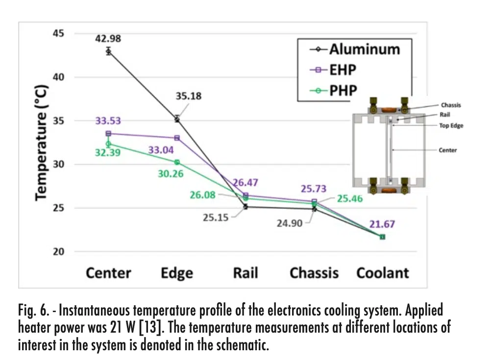
Figure 6 shows steady state temperature profiles of the electronics cooling system using different heat spreaders: aluminum plate (conventional), EHP and PHP. The maximum temperature on the aluminum spreader was ~43°C, while the EHP and PHP reduced the maximum temperature by 9.5°C and 10.6°C, respectively. In the EHP, temperature spreading from the center to edge was better than with the PHP. But the temperature drop from the edge to the rail was higher with the EHP because the heat transfer through the stepped plane was augmented by the fluid channels.
In the EHP, heat flows through the stepped plane only by material conduction. Overall, the EHP and PHP-based cooling system showed very similar performance with approximately twice the thermal conductance relative to the baseline (i.e. aluminum plate) cooling system.
Conclusions
Thermal management of modern electronics dissipating large heat fluxes will require employing advanced cooling systems compared to the conventional technologies, such as aluminum conduction plate heat spreaders and conventional wedge-loks. Two forms of advanced heat spreaders: Embedded Heat Pipe (EHP) and Pulsating Heat Pipe (PHP) were presented as superior heat spreaders compared to aluminum spreaders. In general, the EHP works with significantly higher thermal conductance compared to an aluminum conduction plate at or above room temperature. In contrast, PHP had high thermal conductance at lower temperatures and heat fluxes. An enhanced wedge-lok card retainer, capable of expanding in two-directions and providing more heat transfer surface area, was shown to improve joint thermal conductance compared to conventional wedge-loks. At a system level, these technologies together can improve the thermal conductance and reduce the maximum temperature on the chips. This can improve the mean time between failure (MTBF) of future electronics and provide significant performance and cost benefits.
References
[1] https://www.1-act.com/thermal-solutions/passive/heat-pipes/hik-plates/
[2] S. D. Garner, “Heat Pipes for Electronics Cooling Applications,” Electronics Cooling 2, 18-23, 1996
[3] R. Graham, “Heat Pipes,” Thermopedia: Begel House, Inc., 2011
[4] https://www.1-act.com/resources/heat-pipe-calculator/
[5] S. Khandekar, M. Groll and V. Luckchoura, “An introduction to pulsating heat pipes,” Electronics Cooling 9, 38-42, 2003
[6] J. Kim and S. J. Kim, “Experimental investigation on working fluid selection in a micro pulsating heat pipe,” Energy Conversion and Management, 205, p. 112462, 2020
[7] B. L. Drolen and C. D. Smoot, “Performance Limits of Oscillating Heat Pipes: Theory and Validation,” Journal of Thermophysics and Heat Transfer, 3 (4), 920-936, 2017
[8] B. S. Taft, A. D. Williams and B. L. Drolen, “Working Fluid Selection for Pulsating Heat Pipe,” in AIAA Thermophysics Conference, Honolulu, Hawaii, 2011
[9] S. K. Hota, K. L. Lee, G. Hoeschele, R. Bonner and S. Rokkam, “Experimental Comparison on Thermal Performance of Pulsating Heat Pipe and Embedded Heat Pipe Heat Spreaders,” in 2023 39th Semiconductor Thernal Measurement, Modeling & Management Symposium (SEMI-THERM), 2023
[10] https://www.1-act.com/products/ice-lok-thermally-enhanced-wedgelock/
[11] M. D. Flannery, J. Schmidt, J. Weyant and K. Thorson, “Thermal Enhancements for Separable Thermal Mechanical Interfaces,” in AIAA: Spacecraft Thermal Management, 2016
[12] A. Slippey, W. G. Anderson, M. C. Ellis, C. Hose, J. Schmidt and J. Weyant, “Thermal Management Technologies for Embedded Cooling Applications,” in 17th IEEE Intersociety Conference on Thermal and Thermomechanical Phenomena in Electronic Systems (ITherm) , 2018
[13] K. L. Lee, S. K. Hota, A. Lutz and S. Rokkam, “Advanced Two-Phase Cooling System for Modular Power Electronics,” in 51st International Conference on Environmental Systems, St. Paul, MN, USA., 2022
[14] S. M. S. Murshed and C. A. N. de Castro, “A critical review of traditional and emerging techniques and fluids for electronics cooling,” Renewable and Sustainable Energy Reviews, 78, 821-833, 2017
[15] C. Y. Tseng, H. M. Wu, S. C. Wong, K. S. Yang and C. C. Wang, “A Novel Thermal Module with 3-D Configuration Pulsating Heat Pipe for High-Flux Applications,” Energies, 11 (12), 3425, 2018
[16] K. L. Lee, S. K. Hota and A. Lutz, “Advanced Cooling System for Modular Power Electronics,” NASA SBIR Phase I Final Report (Distribution B) Contract#80NSSC21C0211, 2021
