Introduction
This article is a use of helpful comparison of common thermal solutions you may want to consider with the overall increase in automation in the electrification of the world. We’ll focus on two distinct segments within the industrial market, one being energy management and the other being automation and control applications such as solar and wind inverters. Uninterruptible power supplies and motor drives or controllers utilize high-power IGBTs. These devices require adequate cooling to operate properly over the life of the product. There’s a significant need to improve thermal performance using air cooling for applications that don’t have access to liquid as a cooling option. There are many reasons for seeking improved thermal performance, such as increased component power, a desire to reduce airflow for improved energy consumption and other technical needs in this market. Being able to innovate and deliver competitive products into the marketplace is crucial.
The heat generated within these applications is a significant barrier to accomplishing product goals considering that some of the latest IGBTs can have higher heat fluxes and powers temperature related failure is certainly a concern. Many have heard the rule of thumb that for every 10°C rise in junction temperature the life of the component will be cut in half. This is simply a rule of thumb and it’s never that simple, but at least it gives a sense for how important it is to maintain appropriate temperatures for your high power components. Other than reliability, many things may also justify further investigation into improving the thermal solution, such as overall size, noise or energy consumption, product cost, reduced maintenance, and other product requirements to gain or maintain a competitive edge.
The Cooling Trends
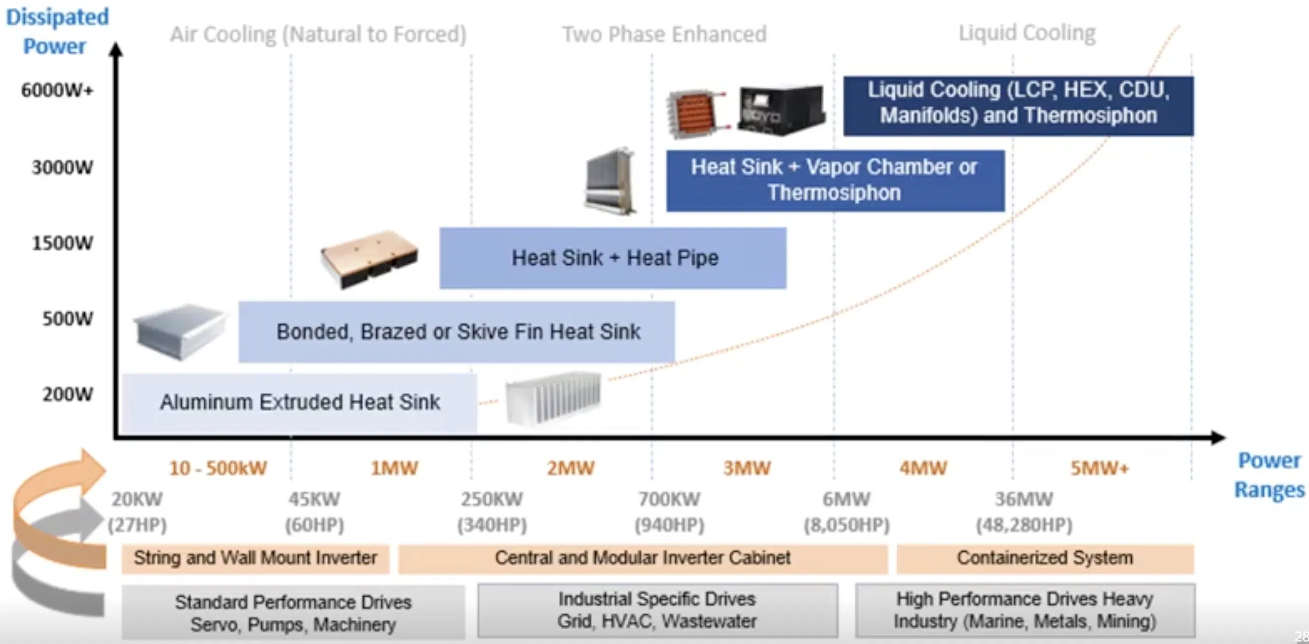
If you’re responsible for working on new designs for these applications, this Figure 1 will be useful. It gives a rough matchup of different types of thermo solutions available with types of systems being cooled. Shown on the Y axis, we’re focused on 200 to 6,000 watt range of dissipated powers from high power components such as IGBTs. On the X axis there are two groups of labels depending on if you’re looking at inverter type cooling in orange or motor drives in gray for the inverters at the low end of the spectrum extruded type product may typically be used. Then as power increases a move to something with a higher fin density like bonded fin or sky fin may be required at that point. If power is getting too high and spreading over the basis of bottleneck, the integration of heat pipes or vapor chambers may be required as power increases, either the size of the solution will need to increase or the use of extreme air cooled solutions such as thermosiphons or even liquid cooling may need to be adopted. The same goes for motor drive systems where the size of the motor being controlled may require higher power drives used in machinery, HVAC or marine and mining applications. As with many thermal solutions, there are typically an overlap and while this chart may be helpful in ruling out some technologies, further detailed study and modeling would need to be completed to select the best choice for your application.

In the image above, we have some of the most common examples of heat sinks with different manufacturing technologies needed to obtain the fin surface area required for forced convection cooling. For most solutions in this space, you’ll notice that aluminum is predominantly used for its low weight and cost. There are different fin geometry limitations based on these manufacturing technologies. For example, aluminum extrusion is more limited with its fin height to fin gap ratio, as well as fin thickness bonded or braised fin, allow the fin in base to be manufactured separately so that after assembly a wider range of fin geometries can be obtained. And finally, sky fin type heat sinks allow for higher fin densities than extrusion without the need for a thermal epoxy or braise joint between the base and the fin.
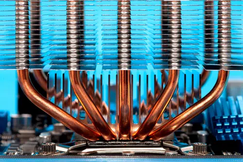
In many applications, the heat sink size relative to the components being cooled can be increased to improve the thermal performance, but at some point the distance between the heat generating component and the surface area dissipating that heat to the air becomes too great leading to poor heat transfer. Heat pipes or vapor chambers utilize the heat of vaporization of a fluid, typically water to quickly evaporate transport and condense in cooler regions, thus spreading that heat over. In some cases, heat pipes may be also utilized to bring heat up to the top of the heat sink to improve the fin efficiency. Depending on the overall size of the thermal solution, if base spreading is not sufficient, spreading the heat over the entire 3D keep in volume, utilizing a thermosiphons may be an option like the heat pipe.
Thermosiphons use a fluid to evaporate and condense to transport the heat. Unlike heat pipes or vapor chambers, these devices typically aluminum filled with a dielectric fluid that utilize gravity as opposed to capillary forces to return the condensed fluid to the evaporator. This type of solution will require early planning to configure your system, allowing for the condenser portion of the keep in volume to be above the evaporator. Lastly, if there is facility water available or you have a cabinet dedicated to closed loop cooling using a CDU, or cooling distribution unit, then cold plates may be used as the final dissipation to air is remote in another cabinet or outside the building. The volume for cooling next to the component is relatively small.
In part two of this series, we will dive into an apples to apples comparison of these technologies in CFD for a typical application.


