Introduction of Bare-Die Jet Cooling in Package
With the rising demand for more powerful, efficient, high-performance computation (HPC) systems, power densities of devices have increased dramatically. To cope with the increasing heat flux challenge for future data center servers beyond 1 kW/cm2, efficient liquid cooling solutions are needed to address those thermal challenges. In the landscape of advanced electronic cooling solutions, various options exist, ranging from embedded microchannel cooling to inter-die layer cooling, encompassing single-phase to two-phase jet cooling.
However, from an industry perspective, challenges associated with direct embedded microchannel cooling, such as escalating costs and reliability issues, currently remain substantial barriers to their implementation in high-power and high-performance chips within data centers. The expensive and high-risk nature of the etching process on the processor backside further complicates matters for chip manufacturers [1].
The bare-die impingement jet cooling solution shown in Fig.1(a) presents a compelling alternative that circumvents the need for postprocessing of the processor backside. In bare die cooling, liquid coolant is directly ejected from jet nozzles on the chip backside, resulting in exceptional thermal and hydraulic performance, lower thermal resistance, and reduced pumping power consumption [2]. These attributes make it highly promising for near-term implementation within industry data center systems. Therefore, system design guidelines are needed to design an energy efficient bare die jet cooling, including the nozzle parameters, manifold optimizations as well as material reliability.
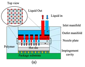
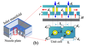
Figure 1: Chip level bare die cooling solutions for high performance system: (a) schematic of the bare die cooling concept; (b) geometry critical dimensions for parameter investigations [2]
In this article, parametric analysis of an impingement cooling geometry is introduced. After that, an innovative manifold design is investigated and compared. Lastly, the packaging processes and material-compatible bare-die jet cooling solutions will be discussed. Figure 1(b) shows a graphical representation of the geometrical parameters of the unit cell for an impinging system with an N×N array of inlet nozzles and distributed inlets with inlet diameter di, outlet diameter do, cavity height H, nozzle plate thickness t, chip thickness tc and unit cell size L. The unit cell size is defined as the ratio between the chip size Sd and the nozzle row number N: L = Sd / N. The chip area in this study is fixed at 8×8 cm2.
Design Guidelines for On Cooler Nozzle Parameters
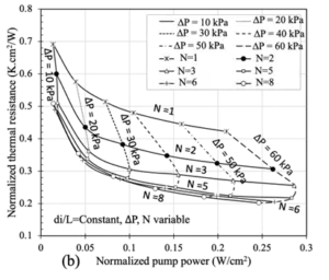
In this study, we investigated different design variables to identify their best combination, focusing on thermal resistance and pumping power independently. A specific cooler’s thermal behavior, with fixed dimensions, was analyzed across various pressure drops and flow rates, represented in Figure 2(a) and 2(b). The thermal resistance scales inversely proportional with the chip size (resulting in lower thermal resistance values for large chips), while the pumping power scales proportionally with the area (resulting in high required pumping power for large chips). To compare the intrinsic cooling performance of the different coolers, all quantities are normalized with respect to the chip area, A. Therefore, the normalized thermal resistance Rth∗ = Rth*A, and the normalized pumping power Wp∗ = Wp/A. Different cooler geometries can be compared on these charts, and the curve closest to the origin represents the Pareto front for optimal thermal solutions. Based on the characteristic curves, the designer can choose the optimal value based on a constrained flow rate or pressure drop. In this study, we used water as the liquid coolant.
Figure 2 indicates a key trend: thermal resistance saturation with increasing nozzle density (N) under constant cavity height. In Figure 2(a), characteristic curves depict the trade-off between thermal resistance (Rth*) and pumping power (Wp*) for various cooler arrays and flow rates (50 mL/min to 530 mL/min). The analysis maintains a constant nozzle diameter ratio (Di/L), ensuring a consistent nozzle area when altering N. The design range for Di/L is from 0.01 to 0.4. Since the Reynolds number ranged from 32 to 2024, a laminar model and transition SST model were used in this study. With a constant flow rate, Rth* decreases as flow rate rises for a fixed N, but pumping power concurrently increases. Notably, an asymptotic behavior emerges for higher N, and the pumping power initially decreases but then grows again as N increases. A similar trend is observed in Figure 2(b) under a constant pressure drop.
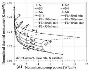
Figure 2: Characteristic curve of the cooler with different nozzle number and (a) flow rate and (b) pressure drop, with Di/L kept constant (Di/L=0.1, H=0.2 mm)
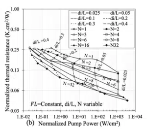
The following steps explore the impact of nozzle diameter in a trade-off chart with constant pressure drop and constant flow rate constraints. The nozzle diameter ratio (Di/L) varied from 0.025 to 0.4, with nozzle number (N) ranging from 1 to 64. In Figure 3(a), with constant N and pressure drop (∆P), thermal resistance decreases as nozzle diameter increases, leading to an increase in pumping power due to higher inlet velocity to meet the fixed pressure drop constraint. Conversely, for a constant nozzle diameter, thermal resistance decreases initially and then increases with rising N, while pumping power decreases with increasing N. Figure 3(b) presents a similar trade-off chart for a constant flow rate, showing different trends compared to a constant pressure drop. For constant N, thermal resistance reduces as Di/L decreases, while pumping power increases due to higher inlet velocity. With constant Di/L, both thermal resistance and pumping power decrease initially and then increase with increasing N.
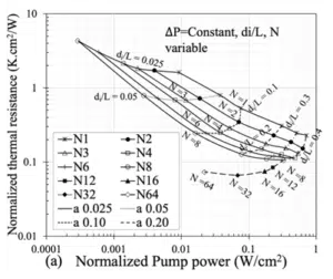
Figure 3: The characteristic curve with different nozzle diameter ratio and inlet number N under (a) constant pressure drop=40 kPa; (b) constant flow rate=530 mL/min, at H=0.2 mm). (Note: a in Fig 3a represents Di/L)
In summary, optimizing the nozzle diameter and number in a jet cooling system has significant effects on thermal performance and pumping power. Varying these parameters allows designers to find a balance, considering factors such as thermal resistance and pumping power, ultimately influencing the efficiency and effectiveness of the cooling system.
Advanced Manifold Level Design Methodology
In a previous study, the importance of the manifold level optimization is discussed [3]. It is shown that the manifold level design of this microfluidic cooler is very important for the overall cooler performance, since it determines the flow uniformity and system level pressure, especially for large area die size applications. Our results indicate that the pressure drop analysis of a 3D printed full cooler level shows that the manifold level is responsible for the majority (80%) of cooler pressure drop, including the inlet and outlet manifold. Furthermore, the inlet manifold defines the coolant flow distribution over the chip [3]. The flow uniformity can further determine the temperature gradient across the chip surface, which is important to improve the design. In this section, three innovative designs are proposed and compared to the initial standard design. These include a mushroom manifold design, isolated jet nozzles and finger-shape manifold design. The thermal and hydraulic performance analyses are based on CFD modeling results.
Mushroom Manifold Design
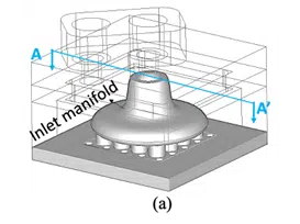
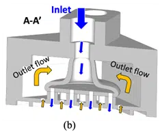
As illustrated in the flow distributions of the multi-jet impingement cooling in Figure 4, the inlet flow goes into the inlet chamber, showing a mushroom shape. However, the flow at the top corner of the manifold introduces significant pressure losses. Therefore, a mushroom shape inlet manifold is proposed to reduce the pressure drop. The CAD design structure is shown in Figure 4 with an internal visualization and the cross-section view of the cooler.
Figure 4: Mushroom manifold design: (a) internal visualization of the mushroom inlet manifold design; (b) cross section view of the new design with indication of the flow directions
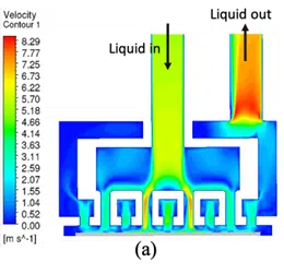
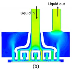
Figure 5: Velocity distribution comparison for the (a) standard cooler design and (b) mushroom design (chip power=50W, flow rate=1 L/min)
For the comparison of the mushroom design and standard design, CFD modeling was used to evaluate the chip temperature and pressure drop. The flow rate used in this comparison is 1 L/min. The chip power of 50 W was applied to the 8×8 mm2 chip. The flow distributions for the two designs are shown in Figure 5. It can be seen that much more design volume space is transferred to the outlet manifold. Moreover, the velocity distribution across the inlet nozzles shows better flow uniformity. The modeling showed that the mushroom design reduced the pressure drop by 40%, and the average chip temperature by 10% for the same temperature gradient, as shown in Table 1.
| Design | Pressure drop (kPa) |
Averaged chip temperature (℃℃) |
Temperature gradient (℃℃) |
| Standard design | 45.1 | 24.9 | 3.4 |
| Mushroom design | 305 | 21.9 | 3.1 |
Table 1: Performance comparison between the standard design and mushroom design
Isolated Nozzles Design
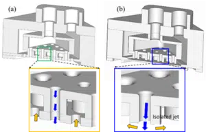
The standard design shown in Figure 6 has locally distributed outlets that provide very short paths to the outlet manifold. However, this requires the outlet flow to pass through outlet nozzles that add significant pressure drop. To eliminate this extra pressure drop, isolated inlet nozzles were evaluated; as shown in Figure 6(b), the outlet nozzles were replaced by an open area inside the manifold.
Figure 6: (a) Initial standard design with locally distributed outlets; (b) Isolated jet for outlet manifold level design.
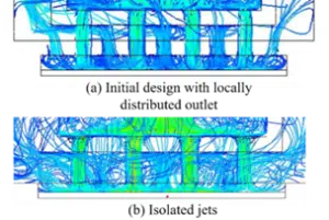
The temperature and pressure drop comparison between the initial vertical feeding design and isolated jet design are compared systematically in Table 2. In general, the isolated jet cooling shows worse thermal performance than the initial design with locally distributed outlets. The initial outlet nozzle plate confines the wall jet region on the cooling surface, resulting a lower temperature. The open area outlet flow for isolated jet cooling can lead to cross flow effects inside the cavity, which can influence the temperature gradient of the chip, shown in Fig.7.
| Design | Pressure drop (kPa) |
Averaged chip temperature (℃℃) |
Temperature gradient (℃℃) |
| Standard design | 45.1 | 24.9 | 3.4 |
| Isolated jet | 42.6 | 26.5 | 9.9 |
Table 2: Performance comparison between the initial design and mushroom design
Figure 7: (a) Initial standard design with locally distributed outlets; (b) Isolated jet for outlet manifold level design
Finger-Shape Manifold Design
Lateral feeding designs show significant advantages relative to vertical feeding designs. However, this design still needs two layers: one for the inlet manifold and the other for the outlet manifold. This conflicts with the need for thinner coolers to be compatible with chip packaging design requirements. Therefore, a finger shape design that combines the inlet manifold and outlet manifold into one manifold layer is proposed (Figure 8). This allows the cooler thickness to be reduced by a factor of 2.8, relative to a conventional lateral feeding design with two layers. The inlet manifold and outlet manifold are separated by the solid wall. A full scale CFD model is also performed for the finger-shape design. The CFD model and meshed model with the fluid domain are extracted from the CAD structure. The flow rate is 1 L/min, under chip power of 50 W.
Figure 8: Schematic of the finger-shape manifold design:(a) entire CAD design structure; (b) snake shape design with local channels
The temperature comparison shows that the thin manifold design with vertical feeding results in a lower temperature in the chip center while the hottest temperature is around the chip corner. For the finger-shape design, the lowest temperature is at the end of the inlet manifold, where we expected recirculation at those locations. The highest chip temperature is at the end of the outlet manifold, showing less flow rate at those locations. In addition, the thermal and hydraulic performance are compared, including the averaged chip temperature, pressure drop and temperature gradient. The finger-shape design shows a 40% thinner cooler (from 5 mm to 3 mm) and the pressure drop reduced by a factor of 2.5. Moreover, the temperature gradient can be improved by a factor of 1.4, as shown in Table 3. In general, the finger-shape manifold design shows great advantages of the cooler thickness and the pressure drop reduction.
| Design | Pressure drop (kPa) | Averaged chip temperature (℃℃) |
Temperature gradient (℃) |
| Standard design | 45.1 | 24.9 | 3.4 |
| Thin manifold design | 163 | 24.7 | 8.1 |
| Snake shape design | 65.0 | 23.2 | 5.8 |
Table 3: Performance comparison between the initial design and mushroom design: use the previous design
Cooler Materials for Reliability Exploration
The bare die jet cooler assembly process offers two cooler assembly options: the first is to assemble the package to the board and then attach the cooler to the package with adhesive or clamping. An advantage of this assembly approach is that it does not introduce a high temperature requirement for cooler material. In the second assembly option, the cooler is first mounted and sealed on the package before the package and cooler are assembled to the PCB. This assembly option introduces the need to survive the reflow temperature (250°C). The exploration of various cooler materials for enhanced reliability encompasses a diverse range of options, such as materials with low CTE and/or, high Heat Deflection Temperature (HDT) and new manufacturing methods. One method involves additive manufacturing techniques with CTE- modified polymer-based materials that can provide flexibility and adaptability in cooler design [4].
In addition, glass-based coolers can offer unique thermal properties and durability [5]. Metal 3D-printed direct liquid jet-impingement cooling stands out as an innovative solution, leveraging advanced manufacturing methods for efficient and precise thermal management [6]. Additionally, ceramic-based coolers contribute to the reliability landscape, bringing high-temperature resistance and mechanical strength [7]. Each of these materials presents distinct advantages, and their exploration underscores the ongoing quest for cooler materials that meet the demanding requirements of reliability in various applications.
Conclusion
This article highlights the potential of bare-die impingement jet cooling for high-performance computing systems. It explores nozzle parameter optimization, advanced manifold design, and various materials for enhanced reliability. The findings demonstrate the importance of achieving a trade-off between the thermal resistance and pumping power while offering innovative manifold design solutions to improve overall cooler performance. The study offers insights and guidelines for thermal engineers in designing efficient and reliable cooling systems for high-performance data centers.
________________________________________________________________________________________________
References:
[1] Wei, Tiwei. “All-in-one design integrates microfluidic cooling into electronic chips.” (2020): 188-189.
[2] Tiwei, T., Oprins, H., Cherman, V., Van der Plas, G., De Wolf, I., Beyne, E., & Baelmans, M. (2017, December). High efficiency direct liquid jet impingement cooling of high-power devices using a 3D-shaped polymer cooler. In 2017 IEEE International Electron Devices Meeting (IEDM) (pp. 32-5). IEEE.
[3] Wei, T. W., H. Oprins, V. Cherman, E. Beyne, and M. Baelmans. “Experimental and numerical investigation of direct liquid jet impinging cooling using 3D printed manifolds on lidded and lidless packages for 2.5 D integrated systems.” Applied Thermal Engineering 164 (2020): 114535.
[4] Fei, Guanghai, Tiwei Wei, Qimin Shi, Yongjian Guo, Herman Oprins, and Shoufeng Yang. “Preliminary study on hybrid manufacturing of the electronic-mechanical integrated systems (EMIS) via the LCD stereolithography technology.” (2019).
[5] Wei, T. Ph.D. thesis (2023). “High Efficiency Polymer based Direct Multi-jet Impingement Cooling Solution for High Power Devices.” arXiv preprint arXiv:2310.11663.
[6] Pappaterra, Antonio, et al. “Advanced (Metal 3D-Printed) Direct Liquid Jet-Impingement Cooling Solution for Autonomous Driving High-Performance Vehicle Computer (HPVC).” EuroSimE. IEEE, 2021
[7] Lin, Yujui, Tiwei Wei, Wyatt Jason Moy, Hao Chen, Man Prakash Gupta, Michael Degner, Mehdi Asheghi, H. Alan Mantooth, and Kenneth E. Goodson. “Multi-level embedded three-dimensional manifold microchannel heat sink of aluminum nitride direct bonded copper for the high-power electronic module.” Journal of Electronic Packaging 146, no. 1 (2024): 011006.
