The previous article in this series on thermocouples described how the size of the thermocouple wire could affect its accuracy [1]. This is particularly true if the wire is exposed to high convection coefficients. This article addresses a separate issue, namely the degree to which the attachment method impacts thermocouple readings. As it turns out, once again the convection conditions used in testing will influence the degree to which the attachment method can affect measurements.
Various researchers have reported the impact of thermocouple attachment on measurement accuracy. For example, an experimental investigation of component temperatures with different thermocouple types, sizes and attachment methods (copper tape and epoxy) [2]. That study found only a 3% reduction in the measured thermal resistance of the part when copper tape was used rather than epoxy. In comparison, using a larger (30-gauge) type T thermocouple led to ~11% error in the thermal resistance measurement compared to a smaller (36-gauge) Type J thermocouple.
In another example of relevant work, a detailed numerical study investigated a wide range of factors that affect thermocouple accuracy [3]. This included the effects of thermocouple type, size, cooling air conditions, and how the thickness and thermal conductivity of the epoxy used to attach the thermocouple to a surface affected the measurement. Their results, for a specific set of external boundary conditions, showed that epoxy bond lines of more than 1 mm could lead to temperature measurement errors of over 30%. The thermal conductivity of the epoxy was also shown to affect the measured temperature by ~5-10% depending on the wire size. Alternatively, mechanical attachment methods such as peening and crimping, can be used to place thermocouples on a surface [4].
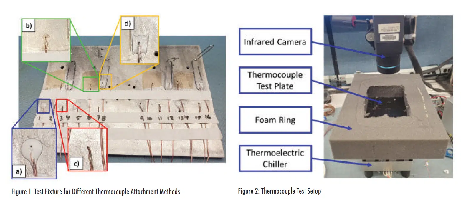
For this article, a test was conducted by attaching type T, 30-gauge thermocouples to an aluminum plate using four different methods, as shown in Figure 1. The four inset images on this figure illustrate the four attachment methods. Inset Figure 1a) shows the thermocouple attached using a standard two-part epoxy. Figure 1b) shows a thermocouple held to the aluminum plate with an adhesive tape. Figure 1c) shows a thermocouple attached to the plate using a fast-curing cyanoacrylate adhesive, i.e., a ‘Super glue’. Finally Figure 1d) shows a thermocouple attached with the same two-part epoxy as in Figure 1a), but with a thicker bond line. As can be seen in the image of the full plate, large paper clips (with wire diameter of ~1mm) were placed on the plate so that the thermocouple beads were suspended above it to assess how much the larger stand-off affects result. Then the epoxy was applied and, after the epoxy had cured, the paper clips were removed. Note that the paper clip are still present in the picture of the full plate but removed for the inset picture d).
Four replicates of each attachment approach were included on the plate with, for example, thermocouples 1, 5, 9, and 13 attached with the conventional approach using two-part epoxy illustrated in Figure 1a), but with a thicker bond line. As can be seen in the image of the full plate, large paper clips (with wire diameter of ~1mm) were placed on the plate so that the thermocouple beads were suspended above it to assess how much the larger stand-off affects result. Then the epoxy was applied and, after the epoxy had cured, the paper clips were removed. Note that the paper clip are still present in the picture of the full plate but removed for the inset picture d). Four replicates of each attachment approach were included on the plate with, for example, thermocouples 1, 5, 9, and 13 attached with the conventional approach using two-part epoxy illustrated in Figure 1a).
After the epoxy had cured, the aluminum plate was painted so that its emissivity was relatively uniform across the entire area. It was then attached to a thermoelectric cooler that maintained the plate temperature at controlled temperatures. The plate temperature was monitored using an infrared camera, as shown in Figure 2. Lab ambient temperature during this testing was ~20°C.
Since initial testing showed that the temperatures were affected by the surrounding conditions, tests were conducted using three different boundary conditions to compare effects. In the ‘Blowing Air’ condition, the plate with the thermocouples was exposed to moderate air flow (~3-4 m/s) from a small fan that was ~1 m away. Figure 2 shows the ‘Still Air’ configuration, in which the fan was turned off and a foam ring was placed on the plate to limit heat transfer from the plate to natural convection and radiation. For the ‘Covered’ configuration, an opaque foam cover was placed on top of the foam ring and the system was allowed to stabilize with minimal convection or radiation from the test plate. Then the cover was removed, and the IR and thermocouple temperatures were quickly collected before the system could respond to the modified boundary condition.
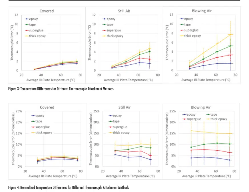
These measurements were done for four different nominal plate temperatures as measured with the IR imager. Test results are shown in Figure 3. The images in Figure 3 show the measurement error of the thermocouples relative to the average temperature of the plate.
In these plots, the error corresponds to the average plate temperature minus the thermocouple measurement, i.e., the thermocouple measurements were always lower than the plate temperatures. Uncertainty bars indicate one standard deviations of the four samples of each attachment method. These data show that, when the plate was covered to minimize heat transfer from its top surface, the four attachment methods produced similar results with ~2°C error when the plate was at ~75°C. However, when the thermocouples were exposed to blowing air, there were substantial differences in the measurement error depending on the attachment method. The thick epoxy had the most significant difference with average offset values of ~8°C at the highest plate temperature. The still air conditions led to less measurement error than blowing air, but the thick epoxy did generate over 4°C error. In each case, the thermocouples with normal epoxy had approximately the same error value, regardless of the boundary conditions.
Figure 4 shows the same data as Figure 3, but the measurement difference is normalized by the temperature rise above ambient temperature1. These results show generally flat lines, which indicate that the relative error for a given attachment method may be constant for a given boundary condition.
Summary
While this testing was relatively crude, it does illustrate that the method used to attach the thermocouple can influence its accuracy. But the degree to which the attachment material affects the results does depend on the test conditions. If the heat transfer through the attachment material is minimized, by insulating the top surface, then the measurement error associated with the attachment method is relatively small. However, if a thermocouple is attached to a surface that is cooled by blowing air or flowing liquid, the conductive thermal resistance through the layer of attachment material will lead to measurement error. The magnitude of this error increases with thicker and lower conductivity attachment.
________________________________________________
1 Tnormalized=(TIR-Tthermocouple)/(TIR-Tambient)
References
- R. Wilcoxon, “Tech Brief – Effect of Thermocouple Size”, Electronics Cooling Magazine, Spring 2024 Issue, pp 9 – 11, https://www.electronics-cooling.com/2024/03/tech-brief-effect-of-thermocouple-size/
- G. E. Tan, C. Carte and Y. Fan, “Thermocouple Attachment Methodology for Memory,” 2021 20th IEEE Intersociety Conference on Thermal and Thermomechanical Phenomena in Electronic Systems (iTherm), San Diego, CA, USA, 2021, pp. 1150-1153
- Q. He, S. Smith and G. Xiong, “Thermocouple attachment using epoxy in electronic system thermal measurements — A numerical experiment,” 2011 27th Annual IEEE Semiconductor Thermal Measurement and Management Symposium, San Jose, CA, USA, 2011, pp. 280-291
- “Attaching Thermocouples by Peening or Crimping”, NASA Tech Briefs, March 1, 2006, https://www.techbriefs.com/component/content/article/1529-ksc-12775


