Previous articles in this series described how thermocouple wire size [1] and thermocouple attachment method [2] can affect steady state temperature measurements. This article briefly discusses how these factors can affect the transient response of thermocouples when used to monitor temperatures that change value over time.
Bare Thermocouple Junction
Before addressing how the thermocouple attachment method affects its transient behavior, it is worth discussing the transient behavior of the thermocouple itself. As described in previous articles, a thermocouple is a welded junction between dissimilar metals that generate a small voltage that is dependent on the temperature of that junction. The welded connection is typically a spherical bead comprised of a mixture of the two metals. This bead is generally small enough that it can be assumed to be fairly uniform in temperature.
The transient thermal response of any mass that is assumed to be uniform in temperature1 can be described in terms of a time constant, τ, where the transient change in temperature of the mass from its starting temperature, ∆T, normalized by the total possible change that the mass will see, ∆Ttotal, can be written as shown in Equation 1:
If the mass is moved from ice water to boiling water, which corresponds to a 100°C temperature change, it would be 63.2°C after one time constant (63.2°C = 100°C*(1-e-1) and 95°C after three time constants.
The thermal time constant of a mass, m, that has uniform temperature at any point in time and has a constant thermal resistance, R, to an external temperature is τ = mcR, where c is the specific heat of the mass. One can estimate the thermal time constant of a thermocouple bead of diameter, D, by considering its mass (m = ρπD3/6), where ρ is the density, and its thermal resistance, R = 1/hA, where the surface area of the bead is πD2. For a sphere that is small enough that it remains close to uniform temperature, the time constant is shown in Equation 2.
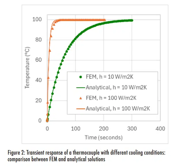
The junction of a type T thermocouple is essentially copper, so its density is 8.9 g/cm3 and its specific heat is 0.39 J/gK (ρc = 3.47 J/cm3K). A 1mm (0.1cm) diameter thermocouple bead in free convection (with h=10W/m2K =0.001W/cm2K) would have a time constant of 58 seconds. In comparison, a smaller thermocouple with 0.25mm diameter in forced air cooling with convection of 100 W/m2K would have a theoretical time constant of 1.4 seconds.
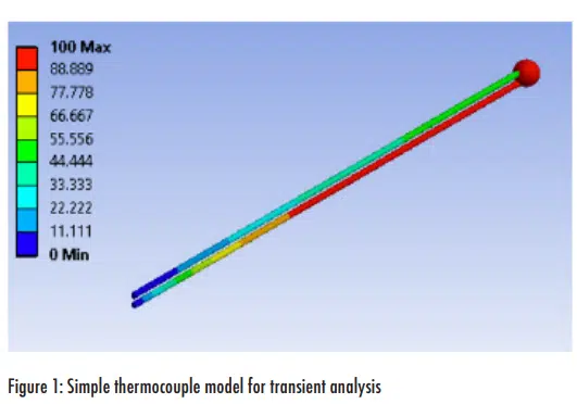
In practice, the thermocouple wires will add mass (that can increase the time constant) and heat transfer area (that can decrease the time constant). To assess the impact of the wire, a simple finite element model (FEM) of a type T thermocouple was created. 2 cm long 30 gauge wires with a 1mm bead were subjected to convection at 100°C after starting at 0°C. Figure 1 shows the model at the end of the 300 second simulation.
Two levels of convection were applied: 10 and 100 W/m2K; Figure 2 shows the results from each simulation are compared to the analytical solution of Equation 2. This shows indicates that the analytical estimate for thermocouple time constant, using only the mass of the bead, is very close to the FEM analysis. As expected, the thermocouple responds more quickly to the external temperature change with better cooling (higher convection coefficient). However, the small difference between the analytical and FEM solutions is somewhat more noticeable with the higher convection coefficient. The FEM analysis slightly slows the response, presumably due a larger portion of the wires being affected by the improved cooling.
Attached Thermocouple Junction
A previous article in this series discussed the effect of thermocouple attachment on steady-state temperature measurements [2]. That testing also revealed some information on how the attachment method can affect its transient response.
Figure 3 shows images of the test fixture and different methods for attaching thermocouples to an aluminum plate. These methods included a) two-part epoxy used in a standard approach, b) a soft tape, c) a quick curing adhesive, i.e. ‘superglue’), and d) the same epoxy as used for a) but applied with a dam (a large paperclip) to create a 1mm thick bondline. The aluminum plate was attached to a thermoelectric cooler (TEC) that could be maintained controlled temperatures.
Sixteen thermocouples were attached to the aluminum plate (four replicates for each of the four attachment methods). For the transient testing, the test plate was covered with foam to minimize thermal loss from its top surface. The TEC was set to maintain a temperature 35°C and allowed to stabilize. The TEC setpoint temperature was then changed to 75°C and the transient temperature response was recorded. The TEC and aluminum plate required approximately five minutes to reach the new setpoint temperature.
Figure 4 shows the average temperature for each thermocouple attachment method and includes a higher resolution image at the ‘knee’ of interest. This shows that the thermocouples with the different attachment methods had fairly similar transient responses.
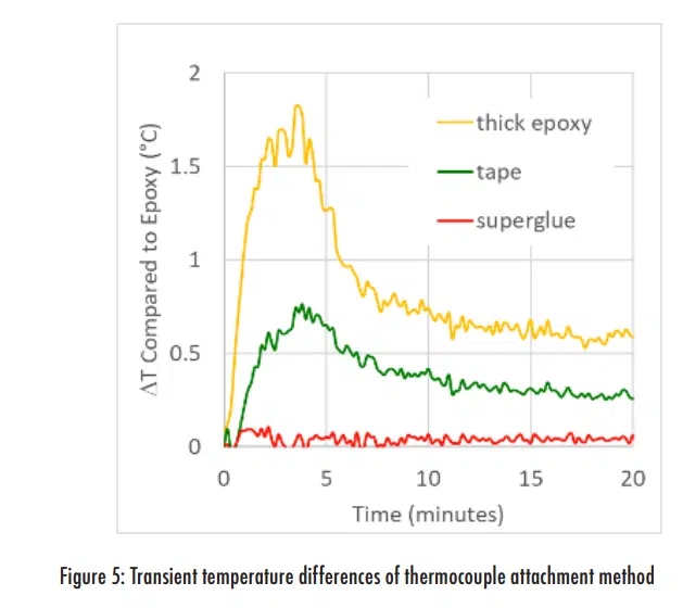
However, there are small, but noticeable, differences between the lines in Figure 4. These differences are illustrated more clearly in Figure 5, which shows the difference between the average temperature for three of the attachment methods relative to the standard method with epoxy.
This plot shows that the transient response with the superglue attachment was nearly identical to the epoxy. However, the other two methods did introduce a small thermal lag that led to a temperature difference between them and the epoxy attachment for a few minutes. Since the responses in Figure 5 are relative to the thin epoxy data, any attachment method that introduces a larger thermal resistance should lead to a slower transient response. However, the thick epoxy does have an unexpectedly larger influence on the transient behavior if one only considers the thermal resistance, given that the resistance for the thick epoxy should still be smaller than the thermal resistance to external cooling air2, which had a time constant on the order of seconds.
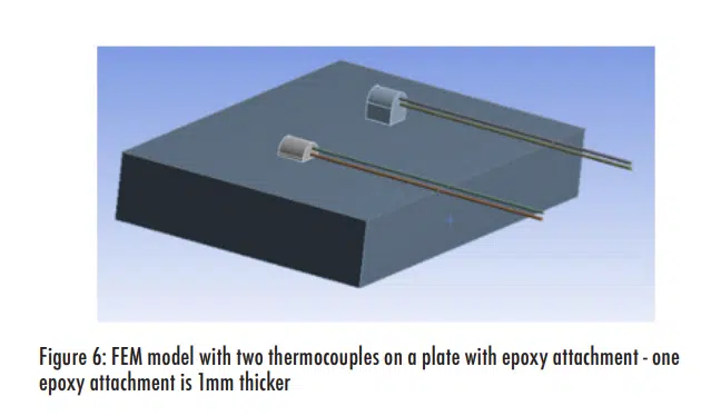
One explanation for transient response with thick epoxy is that the epoxy itself has thermal mass and specific heat. While the resistance may be lower, the thick epoxy represents additional mass that must change temperature along with the thermocouple. To assess this, the FEM model was modified to add an aluminum plate and primitive bodies to represent epoxy. Figure 6 shows an image of the model.
The model was run with the temperature at the bottom of the plate changing by 40°C over a five minute period, which is similar to the experimental transient test conditions. Average temperatures of the thermocouple beads as a function of time are shown in Figure 7, which includes an insert that plots the difference in temperature of the two beads as a function of time. The vertical magnitude of the ‘bump’ in temperature difference in the insert plot is similar to what was experimentally measured.

Summary
The analytical solution for the transient response of a thermocouple shows that its time constant is proportional to its diameter and the thermal resistance between the thermocouple bead and the object whose temperature is being measured. A simple finite element model confirmed the reasonableness of the analytical solution and that the time constant of a small thermocouple in air will have a time constant on the order of a few seconds at most, depending on the convection coefficient.
When a thermocouple is attached to a surface, even a poor attachment method will have a lower thermal resistance to the object being measured than the same thermocouple being convectively cooled. Therefore, the attachment method generally would not be expected to have a significant effect on the transient response for a step change in temperature. However, the attachment material can add mass to the thermocouple bead and potentially increase its thermal time constant, which reduces its transient response.
References
- R. Wilcoxon, “Tech Brief – Thermocouple Size Effects”, Electronics Cooling Magazine, Spring 2024 Issue
- R. Wilcoxon, “Tech Brief – Thermocouple Attachment Effects”, Electronics Cooling Magazine, Summer 2024 Issue
- F.M White, (1984) “Heat Transfer” , Addison-Wesley, pp. 163


