Thermal characterization plays a vital role in electronic package reliability testing, design, and verification of manufacturing processes. The reliability of electronic packages is controlled, in part, by ensuring the maximum junction temperature is not exceeded during operation. Systems such as cell phones, electric vehicles and computers, must operate with die temperatures below their maximum allowable temperature. A clear definition of thermal metrics used to characterize thermal performance is needed to exchange necessary design information between electronic package manufacturers, system designers and reliability engineers. This study compares steady-state and transient methods used to measure component junction-to-case thermal resistance, Theta-JC. Transient Theta-JC measurements tend to predict lower thermal resistance compared to steady-state Theta-JC measurements when multi-directional heat flow paths are present.
Comparative Metrics Versus Predictive Models
Comparative metrics are used to contrast the performance of one device to another while operating under the same conditions, see for example the thermal metrics developed by the JEDEC JC-15 Thermal Characterization committee [1] and the AQG-324 guideline [2].
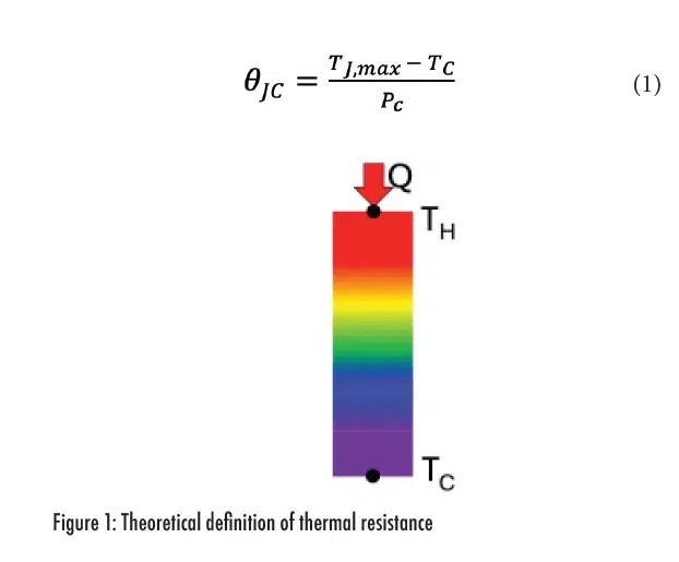
Thermal resistance is a metric commonly used as an electrical circuit analog to represent heat flow restrictions in thermal systems. In an electrical environment, a voltage drop occurs when current flows through a trace of a given resistance. Since the electrical resistivity of a typical insulator surrounding a trace is at least 10 orders of magnitude higher than the trace, for all practical purposes, current only flows through traces. In contrast, the thermal resistance of insulators surrounding thermally conducting materials is only perhaps 3 orders higher. Due to lower resistance, heat spreads more readily into thermal insulators than current into electrical insulators. While it is therefore difficult to make the argument of one-dimensional conduction for thermal applications, in the purest sense, thermal resistance is defined as the temperature drop between a hot isothermal plane, TH, and a cold isothermal plane, TC, divided by the heat flow, Q, as shown in Figure 1. A good overview of the limitations of the thermal resistance concept is discussed by Lasance [3]. Actual semiconductor packages do not have isothermal planes nor does heat flow in a single direction. Despite these limitations, thermal resistance is still a useful concept in developing a comparative metric to contrast the thermal performance of different packages.
Theta-JC, also written as θjc or Rjc, is a comparative metric used to define the thermal resistance between the die and the semiconductor package case. It is defined by Equation (1) where Tj,max is the maximum junction temperature, TC is the outer case surface temperature measured directly above the hot spot on the die and Pc is the power flowing through the case surface.
Significant errors may result when comparative metrics, such as Theta-JC, are used as predictive models. It is tempting to rewrite Equation (1) to predict Tj,max for a different set of application conditions, where Ptot is the total dissipative power.
The problem with applying Equation (2) to predict Tj,max is that Theta-JC is measured during characterization tests in which power is only conducted to the case. However, in Equation (2), Tj,max estimates are made using the total power flowing in more than one direction as usually happens in operation. Also, when Equation (2) is applied to predict Tj,max for an application that utilizes a different heat sink design, errors will result due to differing heat flow paths. It is therefore important to use comparative metrics only to compare the performance of one package design to another when considered in the same testing conditions.
Predictive models must consider more than one heat flow direction. Examples of steady-state predictive models include the two-resistor model [4] and the Delphi thermal network model [5]. For the more general transient cases, reduced order models (ROM) [6] or full order models (FOM) may be used to accurately predict junction temperatures for different application environments.
Steady-State Thermal Resistance
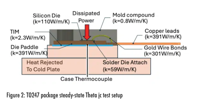
The first Theta-JC test considered here is based on a steady-state method, see MIL-STD-883E [7]. Electrical power is supplied via a current source to the die and the virtual die temperature is measured by reading a temperature-dependent voltage drop at the die, e.g. for a MOSFET between drain and source, see JESD51-1 [8]. Figure 2 shows an example of a steady-state Theta-JC test setup for a leaded discrete device.
Power that doesn’t flow into the case, PNC, includes the heat flowing into the motherboard, power leads or other surfaces, and is not included in the calculation of Theta-JC.
An estimate for PNC may be made by running the Theta-JC test using the same setup but with the cold plate replaced by an insulating block. Ptot is adjusted to produce the same Tj,max as measured during the cold plate test. Using a well thermally insulated block, Pc may be approximated as zero and PNC will be approximately equal to Ptot. This method may be used to test improvements to thermal insulation and test boards designed to minimize PNC.
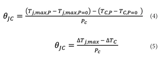
Experimental measurement errors in calculating Theta-JC can be reduced by using the temperature differences referenced to a zero-power condition. Equation (4) is equivalent to Equation (1) since at the zero power condition, Tj,max,P=0 equals TC,P=0.
Measuring the case temperature is challenging for high power packages, due to the large temperature gradient in the thermal interface material (TIM). Moreover, there are large temperature gradients across the case surface at a location directly below the die. These spatial temperature variations make it difficult to repeatably measure case temperature with a temperature probe.
Transient Theta-JC Measurement
To overcome the experimental uncertainty in measuring case temperature, a second method called transient dual interface method (TDIM) was developed, see JESD51-14 [9]. TDIM is applicable for packages that exhibit one-dimensional heat flow where PNC is approximately zero and PC = Ptot. A transient impedance, defined in Equation (6), tracks changes in junction temperature as a function of time. Note the similarities between Equations (1) and (6). A step change in power at times greater than zero is applied and the corresponding junction temperature is measured.

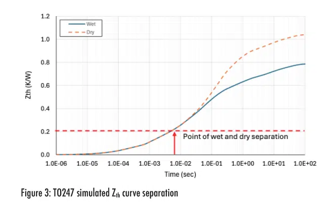
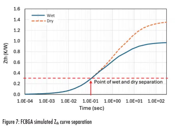
The time at which the transient thermal wave reaches the case can be determined by testing the same package twice. The first test uses a higher resistance TIM and the second test uses a lower resistance TIM, referred to as dry and wet TIM, respectively. At early times, before the thermal wave reaches the case, Zth follows the same curve for both dry and wet TIMs. Once the thermal wave reaches the case, Zth increases at a greater rate for the dry TIM compared to the wet TIM, as shown in Figure 3.
The Zth value at the point of separation of the dry and wet curves may be used to estimate Theta-JC. A more detailed description of this method is given in JESD51-14 [9]. The major requirement for the application of the TDIM Theta-JC measurement is one-dimensional heat flow. This requirement is rather restrictive and typically only applies to die that are mounted to a low-resistance heat spreader with a high-resistance thermal path in the opposite direction. The TO247 and micro lead frame (MLF) are examples of electronic packages that exhibit one-dimensional heat flow. If the heat flow path is multi-dimensional, values of Theta-JC measured by TDIM tend to be lower than Theta-JC measured by the steady-state method.
Experimental Measurements
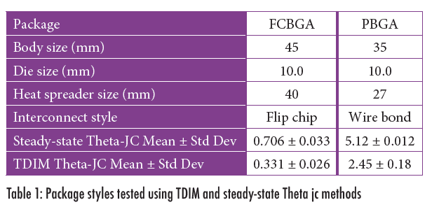
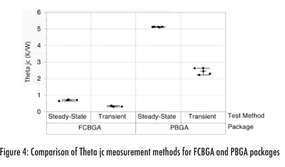
Experimental Theta-JC measurements were performed on two thermal test vehicles (TTVs) to compare TDIM and steady-state measurements. The first TTV is a flip chip ball grid array (FCBGA) package and the second TTV is a wire bond plastic ball grid array (PBGA) package. Details for each package are listed in Table 1. Both package styles experience multi-dimensional conduction, i.e., heat flows both to the case and to the motherboard side of the package. It is known that TDIM Theta-JC values will be lower than steady-state Theta-JC values, see for example Bornoff [10], due to the multi-dimensional heat flow that is not accounted for when using TDIM. TDIM measured Theta-JC is approximately 2X lower than steady-state Theta-JC measurements, as shown in and Figure 4. Error bars shown in Figure 4 represent ± one standard deviation.
Since the focus of this study is the application of comparative metrics, the actual Theta-JC value is less important than the precision in measuring changes in its value. Measurements should be repeatable regardless of the measurement method, but a consistent testing approach is required, for either a transient or steady-state Theta-JC method. For the FCBGA and PBGA packages tested, both the transient and steady-state methods yielded repeatable Theta-JC measurements.
What Causes TDIM Theta-JC To Be Lower Than Steady-State Theta-JC?
Finite Element Analysis (FEA) simulations are used to explain why the measured TDIM Theta-JC values are similar to steady-state Theta-JC values for one-dimensional conduction, and smaller when multi-dimensional conduction is present.
Thermal simulations were run for the TO247 package shown in Figure 2 to predict the Zth versus time. The model consists of a die bonded with solder to a die paddle that acts as a heat spreader. The package has three leads: the source, the drain and the gate. The package is overmolded with a low conductivity epoxy. A TIM is inserted between the exposed surface of the die paddle and the cold plate. A uniform heat flux is applied to the top surface of the die and a large convective heat transfer coefficient, e.g. 1000W/m2, is applied to the base of the cold plate.
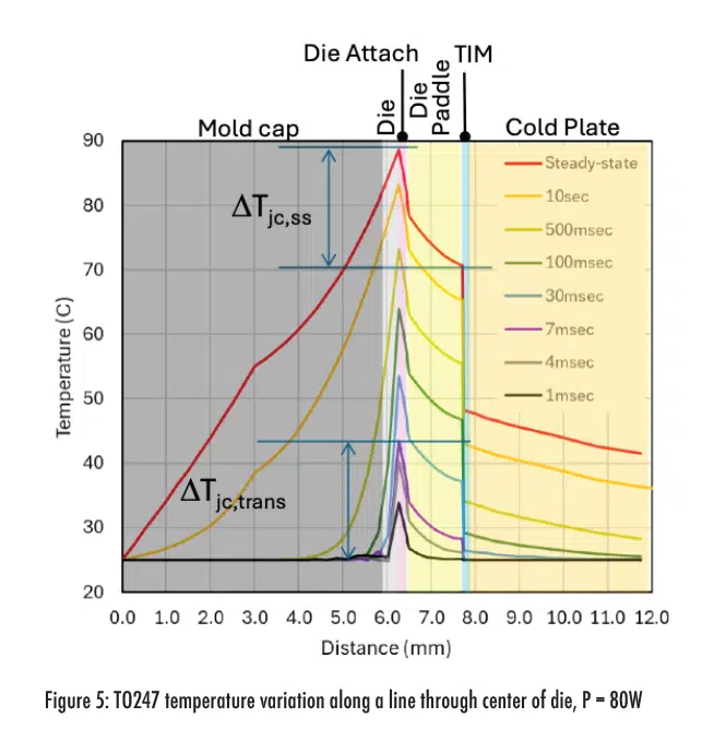
Temperature distributions are plotted in Figure 5 for different distances measured from the top of the mold cap vertically along a line centered at the die. At approximately 7msec, the case temperature begins to increase above its initial zero power temperature. At this time, the wet and dry curves in Figure 3 separated and the Zth predicted by Equation (5) is equivalent to Theta-JC predicted by Equation (1) since Tc = Tj,t=o.
At later times, the temperature difference between the case and junction remains constant, even after reaching steady-state conditions, see at early times is approximately equal to
at later times. For the TO247 package, over 99% of heat flows into the cold plate with the rest flowing to the top of the package or the leads.
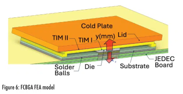
The transient analysis was repeated for the FCBGA package shown in Figure 6. Unlike the TO247, there are two resistance paths having similar orders of magnitude: one to the cold plate and a second to the JEDEC board.
At the point of separation of the wet and dry Zth curves, at approximately 0.1sec as shown in Figure 7, Zth is approximately 0.30K/W.
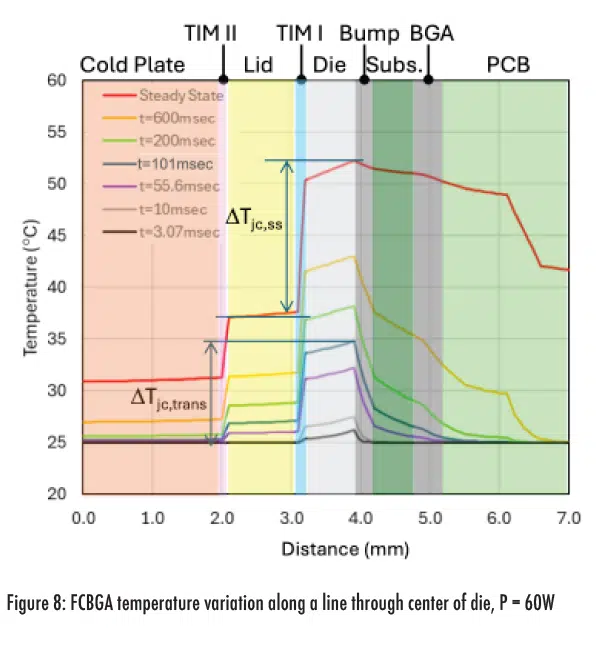
Temperature distributions along a vertical line centered at the die were predicted at several times ranging from 3.07msec to steady state, see Figure 8. At 101msec, the case temperature begins to increase at the same point in time when the dry and wet curves separate as shown in Figure 7. At steady state the temperature difference between the junction and case, is higher than the transient temperature difference,
. The junction-to-case temperature difference for steady-state is
=15K compared to transient
= 9K, as shown Figure 8.
The large difference between TDIM and steady-state Theta-JC is attributed to multi-dimensional heat flow. The two-resistor model discussed in JESD51-3 [4] may be used to indicate if multi-dimensional heat flow is present. Theta-JC represents the restriction of heat flowing to the case and Theta-JC represents the restriction of heat flowing to the motherboard. When Theta-JC is much larger than Theta-JC, heat flow is primarily one-dimensional to the case. Bornoff [10] showed that, when Theta-JB is at least 10X larger than Theta-JC, multi-dimensional heat flow effects are small and TDIM Theta-JC is similar to steady-state Theta-JC.
Theta-JB predictions for the package shown in Figure 6 are approximately 6 times the Theta-JC value. Due to multi-directional heat flow, a large difference between transient and steady-state Theta-JC can be expected.
Steady-State Theta-JC Testing Criteria
When running steady-state tests for certain packages the temperature difference between the junction and case is 30K or more while the temperature drop between the case and cold plate is less than 4K. Even though probing the case temperature introduces measurement errors, the Theta-JC error can be managed by establishing a minimum Theta-JC limit.
A minimum steady-state test condition is developed by requiring the TIM resistance be less than 10% of the measured Theta-JC so that by applying this constraint, the TIM temperature drop is no more than 10% of the junction to case temperature drop. Likewise, from Equation (5), the term uncertainty attributed to the case temperature is limited to less than 10% of Theta-JC.
A conservative estimate for the TIM thermal resistance is made by assuming one-dimensional heat transfer through the TIM bond line thickness, L, and thermal conductivity, KTIM, with an effective area equivalent to the die area, Adie. In practice, spreading within the package increases the effective heat flow area. An approximation for the thermal resistance in the TIM layer is written in Equation (7).
Solving Equation (7) for gives a lower limit on the ratio of bond line thickness to TIM conductivity (L/KTIM) for a given die size, as shown in Equation (8).
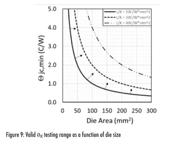
The metric is used to estimate minimum Theta-JC values allowable as a function of die area. Regions to the right of a given L/K line in Figure 9 meet the minimum Theta-JC, criteria given by Equation (8).
For high power and small area die, the large heat flux near the case temperature sensing location will cause a localized high temperature gradient in the TIM layer. Due to the uncertainty in case temperature measurements, there are restrictions in steady-state Theta-JC measurements for small area die. For example, the minimum die area allowable for = 2.0°C/W in Figure 9 is 100mm2, provided L/K = 20°C/W*mm2. Thermal greases have been reported to have L/K of 17-35°C/W mm2 [11].
The thermal conductivity used in Equation (8) is an effective thermal conductivity and includes the contact resistances at the interfaces between the TIM layer and the case and the cold plate.
Another challenge for measuring the case temperature is the presence of gradients in the TIM and across the case surface below the die. A good discussion of the challenges of measuring case temperature with a thermocouple is found in Pape, et.al. [12].
For certain package styles, case temperature measurement uncertainty can be reduced by embedding a temperature sensor into the case. For example, if the package has a case thickness greater than 1mm, then a fine gauge (0.5mm diameter) temperature sensor can be flush mounted to the outer surface of the case, see for example Galloway and de los Heros [13].
__________________________________________________________________________________________________
Conclusions
- Theta-JC may be used as a comparative metric for measuring relative thermal performance improvements between different suppliers or comparing thermal enhancements of different bill of materials.
- Theta-JC can be used to quantify degradation in thermal performance as function of repeated stress conditioning.
- Theta-JC measurements should be repeatable.
- TDIM and steady-state Theta-JC tests may produce different values depending on the presence of multi-directional heat flow.
- When comparing thermal performance of two or more packages, the same testing method should be employed, i.e. do not mix steady-state and TDIM test results.
- Steady-state Theta-JC test methods should be used with caution when Theta-JC is in the region to the left of curves shown in Figure 9.
_________________________________________________________________________________________________
References
[1] JESD51-12, “Guidelines for Reporting and Using Electronic Package Thermal Information”, November 2012.
[2] ECPE Guideline AQG 324 Qualification of Power Modules for Use in Power Electronics Converter Units in Motor Vehicles, March 2021, https://www.ecpe.org/index.php?eID=dumpFile&t=f&f=30359&token=cbab0d6a7844bb815684bcae699892313b924ddb
________________________________________________________________________________________________
Authors
Jesse Galloway, Reliability and Thermal Engineer Consultant
Jesse Galloway received his PhD in Mechanical Engineering in 1991 from Purdue University in West Lafayette, Indiana. His graduate research focus was on experimental and theoretical boiling heat transfer. After graduating, Jesse worked as a thermal engineer at Motorola, Fujitsu and Amkor and most recently as a reliability engineer at onsemi. Currently Jesse is a consultant living in Florida. His work experience includes predicting the reliability of electronic systems, thermal characterization, thermal design of heat sinks and experimental testing. He has published more than 30 conference and journal articles and has been granted 6 patents.
Robin Bornoff, Innovation Roadmap Manager
After receiving a bachelor’s degree in Mechanical Engineering in 1992 and a PhD for CFD research in 1996 from Brunel University in the UK, Robin joined Flomerics as a Flotherm support and application engineer. By the time of the acquisition of Flomerics by Mentor Graphics in 2008 he was the Product Marketing Manager for Flotherm. Now in Siemens Digital Industries Software, he is an Innovation Roadmap Manager in the Simulation and Test Solutions division. With over 25 years experience in the field of electronics thermal simulation, he has published over 30 journal and conference papers and has had 7 patents granted.

