Most engineers involved with temperature measurement know there are several methods for measuring temperatures of fluids and solids. The oldest and most common method for measuring the temperature of a fluid such as air is the standard mercury-in-glass thermometer. However, this is not acceptable for measuring surface temperatures of solid objects. For surface temperature measurements, thermocouples, RTDs, thermistors and infrared devices are the devices of choice.
The selection of surface measurement device should consider the characteristics and costs of the various sensors as well as the available instrumentation. Thermocouples are inexpensive, very rugged and can measure temperatures over a wide range of temperatures. However, they are not as accurate or stable as RTDs and thermistors.
RTDs are subject to inaccuracies from self-heating since they require the use of electric current to make measurements. Thermistors are more accurate than thermocouples and RTDs but are also subject to self-heating since they also require the use of electric current to make measurements. In addition, they have a much more limited temperature range.
Infrared devices have no effect on the surface temperatures of the object being measured but have to be calibrated for the emissivity of the object and the object must be visible to the infrared device. Optical access is a problem when trying to measure device temperatures of objects inside of an enclosure.
What is a thermocouple?
A thermocouple is a sensor that measures temperature. It can be used to measure both the surface temperatures of objects and fluid temperatures. It consists of two different types of metals, joined together at one end. The location where the wires are joined is known as the junction. At the junction a voltage is created that can be correlated back to the temperature.
Thermocouples are commonly used in a wide range of applications. It is important to understand the basic structure of the thermocouple and their ranges in order to select the right type of thermocouple for an application.
How does a thermocouple work?
When two wires of dissimilar metals are joined at together, the joined ends form what is known as a junction. When the junction is exposed to a given temperature, a voltage is generated. This is known at the Seebeck effect. The Seebeck effect is a function of the junction temperature and the composition of the two metals. The voltage that is produced as the junction changes temperature can be correlated to the temperature.

Thermocouple Types
Types J, K, T, E and N are fairly common and are considered base metal thermocouples. Less common are types R, S, C and GB. These are known as the noble metal thermocouples and are used for high temperature measurements.
How to choose a Thermocouple
Determine the application where you will use the thermocouple sensor. Selecting the right thermocouple for your purposes starts with knowing exactly how and where you want to use it.
Determine the required temperature range. Once you know the temperature range that you need, you can refer to a thermocouple range chart to determine which thermocouple type is best. Type K thermocouple offers a wide temperature range and is the type most often used. Type T thermocouples are best for low temperatures.
Determine if a fast response time is important. There are three types of thermocouple junctions: exposed, grounded and ungrounded. An exposed junction provides the fastest response times. An ungrounded thermocouple offers the slowest response time but may be the best choice if it is desirable to have the thermocouple electrically isolated from and shielded by the sheath.
Is there a need for chemical, abrasion or vibration resistance? An exposed thermocouple is limited in use to noncorrosive applications. Both a grounded or ungrounded thermocouple can be used in corrosive or high-pressure environments, but an ungrounded probe is best if there is a need for the thermocouple to be electrically isolated from and shielded by the sheath. If faster response times takes priority in a corrosive environment, then a grounded thermocouple is best.
Installation requirements. The thermocouple may need to be fit with existing equipment. For example, existing holes may determine the allowable probe size.
Thermocouple Accuracy
Type T thermocouples have the tightest accuracy of all the base metal thermocouples at ±1C or ±0.75% of the temperature (in ºC), whichever is greater. Table 1 shows the accuracy and temperature ranges of several types of thermocouples.
| Thermocouple Conductor Type | Limits of Error (Whichever is greater) Solder | Temperature Range | |
|---|---|---|---|
| Standard | Special | ||
| Type K | ±2.2C or ±0.75% | ±1.1C or ±0.4% | -200° to 1250°C |
| Type T | ±1.0C or ±0.75% | ±0.5C or ±0.4% | -250° to 350°C |
| Type J | ±2.2C or ±0.75% | ±1.1C or ±0.4% | 0° to 750°C |
| Type N | ±2.2C or ±0.75% | ±1.1C or ±0.4% | -270° to 1300°C |
| Type E | ±1.7C or ±0.5% | ±1.0C or ±0.4% | -200° to 900°C |
| Type S | ±1.5C or ±0.25% | ±0.6C or ±0.1% | 0° to 1450°C |
| Type R | ±1.5C or ±0.25% | ±0.6C or ±0.1% | 0° to 1450°C |
| Type B | ±0.5% | ±0.25% | 0° to 1700°C |
Table 1: Thermocouple Accuracies and Temperature Ranges
The Seebeck effect, mentioned previously, depends on the alloy combinations used for the thermocouple wires and the temperature of the thermocouple junction. The different metals react differently to temperature, creating a measurable electrical potential that corresponds to the temperature at the junction; the hotter the junction, the higher the voltage produced. By measuring the voltage generated, you can determine the temperature at the junction. The voltage produced by a thermocouple is typically very small (millivolts) and needs to be read by a sensitive instrument to accurately determine the temperature. Table 2, below, shows the alloy combinations used to make popular thermocouples. It also gives the mean thermal conductivity of the alloy combinations. This thermal conductivity will become very important when determining the accuracy of the temperature measurement when investigating the effect of techniques used to mount the thermocouple on the object to be measured.
| Thermocouple Conductivities | ||
|---|---|---|
| ANSI Code | Alloy Combination +/- | Mean Thermal Conductivity (W/mK) |
| K | Ni-Cr/Ni-Al | 24.5 |
| T | Cu/Cu-Ni | 204 |
| J | Fe/Cu-Ni | 44.5 |
| N | Ni-Cr-Si/Ni-Si-Mg | 21.4 |
| E | Ni-Cr/Cu-Ni | 20.3 |
| R | Pt-13%Rh/Pt | 54.2 |
Table 2: Thermocouple Alloy Combinations and Mean Thermal Conductivity
Thermocouple Mounting Techniques
Thermocouples can be mounted either to the surface of the object being measured or internal to the object being measured. Figure 2 shows two different types of surface mounts.

Note that the intrinsic attachment method can only be used on electrically conductive bodies and the two thermocouple wires must be close to each other and electrically attached to the body. The most common surface mount technique is to attach the junction bead of the thermocouple to the body being measured.
For the following study of thermocouple mounting techniques, an experimental setup shown in Figure 3 was made by heating a copper block with an embedded thermocouple. The imbedded thermocouple provides the most accurate temperature measurement of an object since the thermocouple junction is placed inside the object being measured and the hole backfilled with a soft conductive material such as indium. This totally surrounds the thermocouple junction so the junction temperature will be extremely close to the temperature of the object being measured.

For the mounting experiments, three 36 AWG type K thermocouples were attached to the top surface of the copper thermal block. The block was made of machined copper (k=386 W/m-K) with a 50 mm square heated section at the bottom and a 27 mm square mounting surface at the top. A Minco heater is used to provide the heat. The sides and bottom of the block were insulated to reduce heat loss. For all practical purposes, the block may be considered isothermal.
Figure 4 shows three type K thermocouples attached to the surface of the block. The left thermocouple was held in place by a piece of tape with the thermocouple bead contacting the surface of the block. The center thermocouple bead was encapsulated with a drop of epoxy (k = 0.2 W/mK) on the surface of the block. The right thermocouple bead was encapsulated in a bead of solder that was flattened and bonded to the block with cyanoacrylate (super glue). To lower the thermal resistance from the heated block to the thermocouple junction it is advisable to use a thermally conductive epoxy with a thermal conductivity in the range of 0.8W/mK.

When the copper block is heated above ambient temperature, the thermocouple junctions also rise in temperature. However, the temperature difference between the surface of the heated block and the thermocouple junction depends on the attachment technique. Figure 5 shows the temperature error of each of the three types of attachment under natural convection conditions. The temperature measurement error is with respect to the embedded thermocouple just under the surface of the copper block.

The thermal resistance of the junction contact with the heated block is poor when using tape to hold the bead in place. Somewhat better is the junction being embedded in epoxy. The lowest thermal resistance contact is the flattened solder bead bonded to the block with cyanoacrylate (super glue).
The reason the junctions do not reach the same temperature as the surface of the copper block is that heat is being conducted out of the thermocouple junction into the thermocouple wires and the contact resistance at the attachment point is different for each thermocouple.
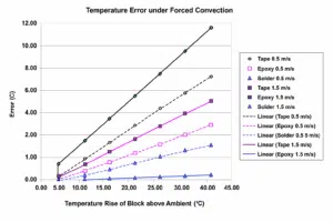
If airflow is introduced across the copper block, the temperature error of the three mounting techniques if much greater. Figure 6 shows the magnitude of measurement error if air is forced over the copper block at both 0.5 m/s and 1.5 m/s. This error is due to the thermocouple wires conducting the heat out of the thermocouple junction and lowering its temperature. No matter what mounting technique is used, the thermocouple junction will always be at a lower temperature than the block when the block is heated above ambient air temperature.
Since the heat convected out of the leads is the main source of temperature error, it is reasonable to assume that the error will be reduced if the leads are covered by tape and held close to the surface of the heated block. Figure 7 shows the leads being covered by tape to reduce their exposure to the air blowing over the wires.

Figure 8 shows the reduction on measurement error with tape covering the first 25 mm of the wire past the junction.

At this point in the study, it is becoming obvious that the thermal conductivity of the thermocouple wire plays an important part in the accuracy of the measurements and that the wires with high thermal conductivity and larger diameter will cause a larger measurement error due to conducting more heat out of the junction.
If you go back to Table 2, you will notice the difference in mean thermal conductivity of the wires between the two most popular types of thermocouples; type K and type T. The mean thermal conductivity of type T thermocouple wire is over 8 times higher than type K. Even though type T is the most accurate thermocouple, unless the junction is totally embedded in the object being measured and the hole backfilled with a high conductivity material, the resulting error caused by heat being conducted out of the junction will be much greater than the inherent accuracy difference between type T and type K thermocouples.
Simulations Comparing K and T Type Thermocouples in a 1 m/s Airflow Environment
A CFD model of a thermocouple using a conductive epoxy attachment was created to compare the magnitude of error that results from using a 30 AWG type K thermocouple vs. a 30 AWG type T thermocouple. The thermocouple junction was embedded in the conductive epoxy and attached to a copper block held at 60ºC. 20ºC air is blowing in the z direction at 1 m/s. The thermocouple insulation is Teflon. The thermal conductivity of the epoxy was set at 0.8 W/m-K compared to a non-conductive epoxy which has a thermal conductivity of about 0.2 W/m-K.

The results of the simulation show that the T type thermocouple has a measurement error of 12.1ºC while the K type thermocouple has an error of 4.4ºC. The magnitude of the error is 2.8 times larger with the T type thermocouple.

Two lessons should be learned from this simulation: The first is the T type thermocouple pulls heat from the junction at a much higher rate due to having a mean thermal conductivity that is 8.3 times greater than the thermal conductivity of the K type thermocouple.

The second lesson is that thermocouples wire should always lay flat against the object being measured and be covered with tape to minimize the heat loss from the wire. In this simulation, 15 mm of tape would have been adequate.
Conclusions
The mounting technique has a significant effect on the temperature error.
The temperature of the thermocouple junction is greatly influenced by the amount of heat being conducted out of the junction by the wires.
Since the junction temperature reading is reduced by heat being pulled out by the wires, lower thermal conductivity wires will result in less error.
The amount of heat conducted out of the junction by the wires is also a function of the diameter of the thermocouple wires. Small diameter wires will conduct less heat out of the junction. The smallest diameter wire should be chosen, taking into consideration the environment and the ease of working with the wire.
The error induced by the accuracy of the thermocouple type is far less than the error induced by the conduction of heat out of the junction through the wires.
References
[1] Omega Temperature Measurement Handbook; Omega Engineering, Inc.
[2] M.H. Attia, A. Cameron, L. Kops, “Distortion in Thermal Fields Around Inserted Thermocouples in Experimental Interfacial Studies, Part 4: End Effect”, Journal of Manufacturing Science and Engineering, February 2002, Vol 124, pp. 135-145.
[3] T.C. Tszeng, G.F. Zhou, “A Dual-Scale Computational Method for Correcting Surface Temperature Measurement Errors”, Journal of Heat Transfer, August 2004, Vol. 126, pp. 535-539.
[4] T.C. Tszeng, V. Saraf, “A Study of Fin Effects in the Measurement of Temperature Using Surface-Mounted Thermocouples”, Transactions of the ASME, Vol. 125, October 2003, pp. 926-935
[5] I. Bluestein, “Understanding Contact Temperature Sensors”, Sensor Magazine Online, January 1999, http://www.sensormag. com/articles/0199/tem0199/main.shtml
[6] N. Keltner, “Heat Transfer Measurements in Electronics Cooling Applications”, Electronics Cooling, Sept 1998, Article 3, http://www.electronics-cooling.com/Resources/EC_Articles/sept98/article3.htm
[7] R.J. Moffat, A. Ortega, “Experimental Methods in Air Cooling of Electronics”, SEMITHERM ’97, January 1997.