 Thermattach thermally conductive adhesivetapes
Introduction
Today’s semiconductors, whether discrete power or logic ICs, are smaller,run faster, do more and generate more heat. Some microprocessors dissipatepower levels that were once the exclusive domain of discrete power devices,namely 10 to 25 watts. These power levels require thermal management techniquesinvolving large capacity heat sinks, good air flow and careful management ofthermal interface resistances. A well designed thermal management program willkeep operating temperatures within acceptable limits in order to optimize deviceperformance and reliability.
Semiconductors are kept within their operating temperature limits bytransferring junction generated waste heat to the ambient environment, usuallythe surrounding room air. This is best accomplished by attaching a heat sink tothe semiconductor package surface thus increasing the heat transfer between thehot case and the cooling air. S. Lee [1] recently described how heat sinks maybe selected to provide optimum thermal performance. Once the correct heat sinkhas been selected, it must be carefully joined to the semiconductor package toensure efficient heat transfer through this newly formed thermal interface.

The rate of conductive heat transfer, Q, across the interface is given by
| Q = | kA(Tc – Ts) —————– L |
where k is the thermal conductivity of the interface, A is the heat transferarea, L is the interface thickness and Tc and Ts are the device case and heatsink temperatures. The thermal resistance of a joint, Rc-s, is given by
| Rc – s = | (Tc – Ts) —————– Q |
and on rearrangement,
| Rc – s = | L —————– kA |
Thus, the thermal resistance of the joint is directly proportional to thejoint thickness and inversely proportional to the thermal conductivity of themedium making up the joint and to the size of the heat transfer area. Thermalresistance is minimized by making the joint as thin as possible, increasingjoint thermal conductivity by eliminating interstitial air and making certainthat both surfaces are in intimate contact.
Attaching a heat sink to a semiconductor package requires that two solidsurfaces be brought together into intimate contact. Unfortunately, no matterhow well-prepared, solid surfaces are never really flat or smooth enough topermit intimate contact. All surfaces have a certain roughness due tomicroscopic hills and valleys as shown in Figure 1A. Superimposed on thissurface roughness is a macroscopic non-planarity in the form of a concave,convex or twisted shape as shown in Figure 1B. As two such surfaces are broughttogether, only the hills of the surfaces come into physical contact. Thevalleys are separated and form air-filled gaps.
| Figure 1. Representation ofsurface irregularity | |
 |
 |
| A. surface roughness | B. Poor surface flatness |
When two typical electronic component surfaces are brought together, lessthan one percent of the surfaces make physical contact. As much as 99% of thesurfaces are separated by a layer of interstitial air. Some heat is conductedthrough the physical contact points, but much more has to transfer through theair gaps. Since air is a poor conductor of heat, it should be replaced by amore conductive material to increase the joint conductivity and thus improveheat flow across the thermal interface.
Several types of thermally conductive materials can be used to eliminate airgaps from a thermal interface, including greases, reactive compounds, elastomersand pressure sensitive adhesive films. All are designed to conform to surfaceirregularities, thereby eliminating air voids and improving heat flow throughthe thermal interface. Some have secondary properties and functions, as well.
Types of Thermal Interface Materials
Thermal greases are made by dispersing thermally conductive ceramicfillers in silicone or hydrocarbon oils to form a paste. Sufficient grease isapplied to one of the mating surfaces such that when pressed against the othersurface, the grease flows into all voids to eliminate the interstitial air. Excess grease flows out past the edges and the thinnest possible thermal jointis formed as the two surfaces come into contact at their high points. Jointintegrity has to be maintained with spring clips or mounting hardware.
Thermal greases are notoriously “user unfriendly”, but providevery low thermal resistance between reasonably flat surfaces. Grease does notprovide electrical insulation between the two surfaces1, and excessgrease that flows from the joint should be cleaned up to prevent contaminationproblems. Greased joints can also dry out with time, resulting in increasedthermal resistance.
The effect of thermal grease on heat transfer through an interface can beseen from the data in Table 1.
| Interface | Thickness, inch | k,W/m-K | Rc-s, °C/W | Rj-a °C/W |
| Dry joint | n/a | n/a | 2.9 | 9.9 |
| Thermal grease | 0.003 | 0.7 | 0.9 | 8.1 |
| Thermal compound | 0.005 | 1.2 | 0.8 | 7.9 |
| Elastomer | 0.010 | 5.0 | 1.8 | 8.9 |
| AdhesiveFilm | 0.009 | 0.7 | 2.7 | 9.6 |
Table 1. Case-sink and junction ambient thermal resistancefor various interface materials. (Pentium Test chip operated at 6 watts undernatural convection cooling with a Wakefield pin fin heat sink)
This data was generated using a P54C Pentium Thermal Test Die powered to sixwatts in an AMP Socket 5. A Wakefield 799-80AB pin fin heat sink was attachedwith a spring clip. Without an interface material, Rc-s was 2.9°C/W. Theaddition of thermal grease to the joint reduced the resistance to 0.9°C/W. Inspection of the joint after testing showed that the grease covered over 90% ofthe area and the thickness was less than 0.07 mm.
Thermally conductive compounds are an improvement on thermal greaseas these compounds are converted to a cured rubber film after application at thethermal interface. Initially, these compounds flow as freely as grease toeliminate the air voids and reduce the thermal resistance of the interface. After the interface is formed, the compounds cure with heat to a rubbery stateand also develop secondary properties such as adhesion. Formulations withadhesive properties do not require mechanical fasteners to maintain theintegrity of the joint.
Since the binder cures to a rubber, these compounds do not have themigration or the dry joint problems associated with thermal greases. Compoundscan be used to fill large gaps where greases would bleed from the joint onaccount of their migratory nature. Clean-up is also simple as excess materialis easily removed after it has been cured to a rubber.
The thermal performance of a typical compound is shown in Table 1. Sincethe compound behaves like a grease, the joint is nearly void free and theimprovement in thermal resistance over a dry joint is similar to that of grease,0.8 vs. 2.9°C/W.
Thermally conductive elastomers are silicone elastomer pads filledwith thermally conductive ceramic particles, often reinforced with woven glassfiber or dielectric film for added strength. These elastomers are available inthickness from about 0.1 – 5 mm and hardness from 5 to 85 Shore A. Unlikecompounds and greases, elastomer pads provide electrical insulation and can beused between surfaces that are at different electrical potential. They aretypically used under discrete power devices where electrical isolation isrequired.
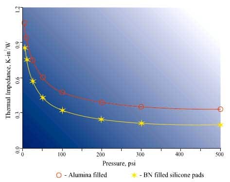
Elastomers do not flow freely like the greases or compounds, but will deformif sufficient compressive load is applied to conform to surface irregularities. Figure 2 shows the effect of applied pressure on the thermal impedance of highdurometer elastomer materials typically used to insulate power devices. At lowpressures, the elastomer cannot fill the voids between the surfaces and thethermal interface resistance is high. As pressure is increased, more of themicroscopic voids are filled by the elastomer and the thermal resistancedecreases. For most high durometer materials, mounting pressures around 300 to500 psi eliminate the interstitial voids and reduce interface resistance to aminimum. Mounting pressure must be permanently maintained by using fasteners orsprings to hold the two surfaces together.
 |
| Figure 2. Applied pressure vs. thermalimpedance |
Table 1 shows the thermal performance of a highly thermally conductiveelastomer at low pressure. Despite a 5 W/m-K thermal conductivity, Rc-s is 1.8°C/W,twice that of grease. Inspection of the disassembled interface after the testshowed that there was less than 30% contact between the material and the twosurfaces.
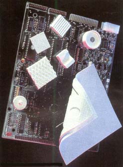
Thermally conductive adhesive tapes are double-sided pressuresensitive adhesive films filled with sufficient ceramic powder to balance theirthermal and adhesive properties. The adhesive tape is usually supported eitherwith an aluminum foil or a polyimide film for strength and ease of handling. Polyimide support also provides electrical insulation. Adhesive tapes performmuch like the elastomeric films, in that they also require some initial matingpressure to conform to irregularities in the mating surfaces. They are alsounable to fill large gaps between non-flat surfaces. However, once the joint isformed, the adhesive tapes require no mechanical support to maintain themechanical or thermal integrity of the interface.
Adhesive tapes provide convenience in attaching a heat sink to a semiconductor package because, unlike liquid adhesives, no cure time isrequired. The film is applied to one of the surfaces, usually to the heat sink,and it is then forced into contact with the semiconductor package to completethe thermal joint. The application pressure is typically 10 to 50 psi for a fewseconds duration. The bond thus formed can be considered permanent and the heatsink is reliably attached to the semiconductor.

However, this convenience comes at a price. As Table 1 shows, Rc-s fortapes is only slightly better than a dry joint. This is because the thermaltapes do not fill gaps as well as liquids, and thermal joints made with tapeswill normally include considerable interstitial air gaps. For the most part,the quality of the two joining surfaces will determine the amount of contactthat can be achieved and the thermal performance that can be expected. The highshear strength of these thermal tapes means that reliable joints between heatsinks and semiconductors can be achieved, even with poor surfaces and nomechanical fasteners.
Conclusion
In summary, a variety of materials and approaches are available to manage orminimize the thermal resistance of semiconductor package-to-heat sinkinterfaces. Thermal greases and compounds will provide the lowest interfaceresistance, but they are pastes and require care in handling. Elastomerseliminate handling problems but they sometimes require high compressive loadseven with well prepared surfaces. Thermal tapes offer great convenience buttheir gap filling properties are limited. The success of any particularcombination of heat sink, interface material and heat sink will depend on thethoroughness of the design, the quality of the interface material and its properinstallation.
1 Thermal greases and compounds generally arenot electrically conductive. However, they do flow from a thermal joint andallow the joining surfaces to make electrical contact.
Dr. Miksa de Sorgo
Chomerics Division of Parker Hannifin
77 DragonCourt, Woburn, MA 01888-4014 USA
Tel: +1 (617) 939 4643
Fax: +1 (617)939 4155
Email: Chomerics@AOL.com
References
1. S. Lee, How to Select a HeatSink, Electronics Cooling, Vol. 1, No. 1 pp.10-14, June 1995


