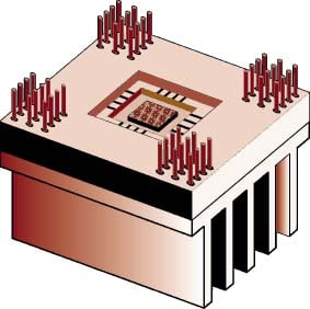
Figure 1. Ceramic Package – Aluminum Heat SinkAssembly
Introduction
The exposed surface area of many of today’s high powered electronic packagesis no longer sufficient for the removal of the heat generated during normaloperation. Heat sinks are a commonly-used, low cost means of increasing theeffective surface area for dissipating heat by means of convective air cooling.While the use of a heat sink lowers the fluid-side thermal resistance, it alsointroduces an interface resistance across the contact formed between itself andthe package case. Under some circumstances, this contact resistance can besubstantial, impeding heat flow and reducing the overall effectiveness of theheat sink. Figure 1 depicts an electronic package heat sink assembly whichwould typically be joined by plastic or metal spring clips around the perimeterof the assembly.
The subject of thermal resistance at interfaces between aluminum heat sinksand ceramic packages has been discussed by Lee [1], de Sorgo [2], Latham [3] andEarly et al. [4]. These articles primarily report test results for jointresistance as a function of contact pressure for various interface types. Theinterfaces examined in these works involve either bare surfaces (air filled) orjoints where the interstitial gap is filled with a material layer containingdispersed thermally conductive fillers. Interstitial material layers currentlyused by the industry, as described by de Sorgo [2], include thermal greases,thermally conductive compounds, elastomers, and adhesive tapes.
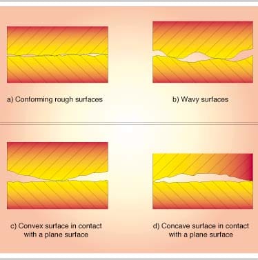
Figure 2. Contact Configurations
The objective of this article is to illustrate how to calculate the thermaljoint resistance for the interface formed by two conforming, rough surfacesshown in Figure 2a, as a function of contact pressure for the low pressurerange, between 0.035 and 0.35 Mpa (5 and 50 psi), commonly encounteredin microelectronic applications (Latham [3]). Peterson and Fletcher [5] verifiedby experiments in vacuum that the following models, which were originallydeveloped for metal-to-metal contacts, give very good results when used topredict the contact conductance at interfaces formed by metals (invar, kovar andalloy 42) and mold compounds (polyset 410B and 410C, MG25F-LMP and MG45F-04) atthe interface temperature range: 20 °C to 70 °C and the interfacepressure range: 0.5 to 5.0 MPa. This work will focus primarily on barejoints, although an example where the interface material is treated as a liquid,such as in the case of a thermal grease, will also be considered. Interfaceswith thermal compounds or elastomeric sheet materials will be shown to be verydifficult to model and will be discussed in general terms only. Thenon-conforming wavy, convex or concave interfaces depicted in Figures 2b, 2c,and 2d, respectively, are exceedingly complex to model and therefore will not beconsidered here. Since radiation heat transfer at most interfaces is negligibleor non-existent, it will not be included in this analysis.
Conforming rough surface model
The thermal joint conductance, hj, of the interfaceformed by two conforming, rough surfaces is given by the following simple modelproposed by Yovanovich [6] and further described and used by Antonetti andYovanovich [7], Yovanovich and Antonetti [8], an and Yovanovich [9].
hj = hc + hg
The contact conductance is given by:
where ks is the harmonic mean thermal conductivity ofthe interface:
ks = 2 k1kSIZE=”-2″>2 /(k1 + kSIZE=”-2″>2)
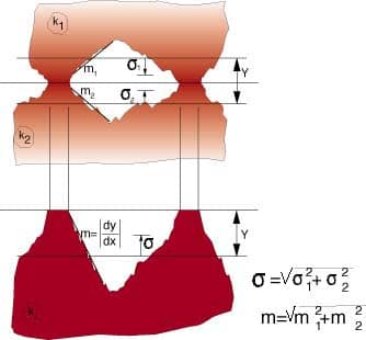
the effective mean absolute asperity slope of the interface m, asshown in Figure 3, is given by:
and where , alsoshown in Figure 3, is the effective RMS surface roughness of the contactingasperities:
The contact pressure is P and Hc is thesurface microhardness of the softer of the two contacting solids. Themicrohardness is in general complex because it depends on several geometric andphysical parameters, such as the Vickers microhardness correlation coefficients.
The surface asperity slope is frequently not given. In this case the meanabsolute asperity slope can be approximated by the correlation equation proposedby Antonetti et al. [10]:
m = 0.125 (SRC=”https://electronics-cooling.com/wp-content/uploads/1997/05/sym_115.gif” width=”10.5″ height=”9.5″> x 106)0.402
which was developed for the surface roughness range:
0.216 µ m < 9.6 µ m
The gap conductance, hg, is given by the approximationof Yovanovich [6]:
hg = kg/(Y + M)
where kg is the thermal conductivity of the gap substance. Theeffective gap thickness Y, shown in Figure 3, can be calculatedaccurately by means of the simple power-law correlation equation proposed byAntonetti and Yovanovich [7]:
Y = 1.53 (P/Hc)-0.097
for the relative contact pressure range:
10-5 < P/Hc < 2 x 10⁻².
The gas parameter M accounts for rarefaction effects at hightemperatures and low gas pressures. This gas-surface parameter depends on thethermal accommodation coefficients, the ratio of specific heats, the Prandtlnumber, and the molecular mean free-path of the gas. Song and Yovanovich [11]present correlation equations for the calculation of the accommodationcoefficients for several gases as a function of the gas temperature. Thiscomplex gas-surface parameter depends on gas pressure and temperature accordingto the relationship:
where M0 denotes the gasparameter value at the reference values of gas temperature and pressure, T0 and Pg,0,respectively. Reference values of the gas parameter for air and helium arepresented in Table 1.
Table 1: Thermophysical Properties of Gap Substances
| Gap Substance | Thermal ConductivityW/(mK) | Gas ParameterM0 x 106, m |
| air | 0.026 | 0.373** |
| helium | 0.150 | 2.05** |
| thermal grease | 0.20 – 0.70* | 0.0 |
| doped thermal grease | 1.68 – 2.58* | 0.0 |
** – T0 – 50 °C, Pg,0 = 1 atm
* – AOS Technical Data Sheets, 1995
Interstitial material layers
Although the conforming rough surface model presented in the previoussection was developed for bare surfaces, it can also be applied to interfaceswith thermal grease. By assuming that the grease behaves as a liquid and fillsall gaps between the contacting asperities, the existing model can be used bysubstituting M = 0 and the thermal conductivity of the grease into thegap conductance relationship. However, when solid interstitial materials areused, such as thermal compounds, elastomers or adhesive tapes, the jointconductance problem becomes much more complicated. As shown in Figure 4, theuse of a solid interstitial material introduces an additional interface to theproblem.
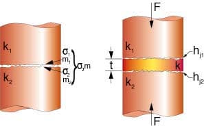
Using thermal resistance concepts, the overall joint conductance for thisproblem is determined by the series combination:
1/hj = 1/(hj,1)+ t/k + 1/(hj,2)
where hj,1andhj,2 refer to the jointconductance between each of the contacting surfaces and the interfacial materialand t andk are the average thickness and thermal conductivity of the layer.Completing this analysis requires characterization of the relevant surfaceparameters, such as the slope, roughness and microhardness, for the variousinterstitial materials. In addition, for elastomeric materials the layerthickness t is not constant but instead depends on the contact pressure.Additional research needs to be done before a model can be developed to addressthis complex phenomenon.
Application to aluminum heat sink-ceramic package interface
Table 2: Thermal and Surface Properties for Aluminum-AluminaConforming Rough Surfaces
| Material | Thermal ConductivityW/(m K) | MicrohardnessMPa | Surface Roughnessµ m |
| A1 5052 [14] | 140 | 745 | 6.9 |
| A1 6061 [14] | 180 | 705 | 0.7 |
| A1 6063-T5 | 201 | 1094 | 0.4 (flycut) |
| Aluminum Nitride [13] | 160 | 10044 | 0.45 |
| Alumina (96% A12O3) | 20.9 | 3100 | 1.3 (ground) |
| Copper [13] | 397 | 924.1 | 0.45 (milled) |
The aforementioned models will be used to calculate the joint resistancesfor the interface formed by an aluminum 6063-T5 aluminum heat sink and Al2O3alumina package. The thermal conductivities of the heat sink and ceramicpackage are k1 = 201 W/m·K and k2= 20.9 W/m·K respectively. The harmonic mean thermalconductivity of the interface is ks = 37.85 W/m·K.Since the microhardness of the aluminum alloy is 1094MPa, which is much less than that of the alumina, it will be used tocompute the contact parameters. Based on a surface roughness for flycutaluminum of 1= 0.4 µ m and a surface roughness for ground alumina of
2 = 1.3µ m, the effective surface roughness of the interface is calculatedas
= 1.36 µm.Since the surface slopes are not given, Eq. (6) will be used to calculate thefollowing values: m1 = 0.139, m2 =0.0865, respectively. The effective surface slope of the interface is thereforem = 0.164. The thermal and physical properties of air, helium andgrease presented in Table 1 will be used in the gap conductance model.
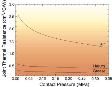
In Figure 5 the joint thermal resistances, whose units are cm 2-°C/Ware plotted against the nominal contact pressure over the pressure range: 0.007P (Mpa)
0.35 for several cases. The bare joint resistances with air or helium presentin the gap are shown. The effect of a thermal grease of thermal conductivitykg = 0.20 W/m·K is also shown in Figure5.
Summary and discussion
Simple correlation equations are presented and used to calculate thermaljoint resistances for a typical aluminum-ceramic interface found inmicroelectronics applications. Flycut and ground surfaces are considered.Joint resistances are calculated for contact pressures between 0.007 and 0.35MPa, which includes the practical microelectronic pressure range of 0.07and 0.17 Mpa (see Latham [3]). The greatest joint resistances are foundwhen air is present in the interstitial gap. In the contact pressure range of0.007 to 0.35MPa, the air joint resistance goes from 2.665 to 1.903 cm2-°C/W.
When silicon grease is placed in the gap, the joint resistance is muchsmaller than the bare interface. The calculated values of the joint resistancelie in the range 0.335 to 0.213 cm2-°C/W which are anorder of magnitude smaller than the joint resistances of a bare joint. Ifgreases with thermally conductive ceramics are used, the joint resistance can bereduced to values below 0.065 cm2-°C/W.
The correlation equations which have been used are based on conforming roughsurfaces with interstitial substances which perfectly wet all portions of thesurfaces which form the gap. Any non-flatness will result in interfaces withlarger gaps which will have larger joint resistances. If the interstitialsubstance does not perfectly wet the contacting surfaces, this will alsoproduce a more thermally resistive interface. The proposed models andcorrelation equations therefore correspond to the best thermal joints which havethe smallest joint resistances.
The use of other interstitial materials, such as thermal compounds,elastomers or adhesive tapes, has been shown to increase the complexity of thejoint conductance problem significantly. In order to successfully model thisproblem, extensive research into characterizing the surface properties and layerthicknesses for the various interfacial materials is required.
References
1. S. Lee, How to Select a Heat Sink, ElectronicsCooling, Vol. 1, No. 1, June 1995, pp. 10-14.
2. Miksa de Sorgo, Thermal Interface Materials,Electronics Cooling, Vol. 2, No. 2, September 1996, pp. 12-15.
3. Carol A. Latham, Thermal Resistance of InterfaceMaterials as a Function of Pressure, Electronics Cooling, Vol. 2, No. 2,September 1996, p. 35.
4. Malcolm Early, Seri Lee, and Mark Pellilo, ThermalPerformance of Interface Material in Microelectronics Packaging Applications,Proceedings of the 1995 International Electronics Packaging Conference,September 1995, pp. 534-544.
5. G.P. Peterson and L.S. Fletcher, Evaluation of theThermal Contact Conductance Between Substrate and Mold Compound Materials, ASMEHTD-Vol. 69, Fundamentals of Conduction and Recent Developments in ContactResistance, edited by M. Imber, G.P. Peterson and M.M. Yovanovich, 1987, pp.99-105.
6. M.M. Yovanovich, New Contact and Gap Correlationsfor Conforming Rough Surfaces, AIAA-81-1164, presented at AIAA 16thThermophysics Conference, Palo Alto, CA., June 1981.
7. V.W. Antonetti and M.M. Yovanovich, Thermal ContactResistance in Microelectronic Equipment, Thermal Management Concepts inMicroelectronic Packaging From Component to System, ISHM Technical MonographSeries 6984-003,1984,pp. 135-151.
8. M.M. Yovanovich and V.W. Antonetti, Application ofThermal Contact Resistance Theory to Electronic Packages, Advances inThermal Modeling of Electronic Components and Systems, Vol. 1, Editors A.Bar-Cohen and A.D. Kraus, Hemisphere Publishing Corporation, 1988, pp. 79-128.
9. M.M. Yovanovich, Theory and Applications ofConstriction and Spreading Resistance Concepts for Microelectronic ThermalManagement, Cooling Techniques for Computers, Editor Win Aung, HemispherePublishing Corporation, 1991, pp. 277-332.
10. V.W. Antonetti, T.D. Whittle, and R.E. Simons, AnApproximate Thermal Contact Conductance Correlation, HTD-Vol. 170,Experimental/Numerical Heat Transfer in Combustion and Phase Change, 1991, pp.35-42.
11. S. Song and M.M. Yovanovich, Correlation of ThermalAccommodation Coefficient for Engineering Surfaces, ASME HTD-Vol. 69,Fundamentals of Conduction and Recent Developments in Contact Resistance, editedby M. Imber, G.P. Peterson and M.M. Yovanovich, 1987, pp. 107-116.

