In the mid 1960’s liquid cooling was deemed necessary by mainframe producers like IBM as the heat flux generated with bipolar circuit technology rose past levels that could be easily managed by traditional air cooling. In the early nineties, a very efficient technology was introduced. Complementary Metal Oxide Semiconductor (CMOS) circuits demonstrated reduced power consumption and, of course, much lower heat flux allowing the industry to easily design air-cooled systems which were less complex and could be made in a very modular fashion. Standards evolved and the computing hardware industry fragmented into a number of computer component manufacturers that specialized in CPUs, GPUs, motherboards, memory, networking and storage. Since the fans could be trusted to blow air across whatever components were integrated, the need for a tightly designed liquid cooling system was eliminated…until now.
If we now look at the fastest computers in the world today, according to Top500.org, 4 out of the top 5 utilize liquid cooling inside the servers. Why? In these examples, it is fundamentally because liquid can enable much higher power density to be dissipated with the added advantage of reducing the cooling costs during their operation. According to a study done by Koomey in 2011, electricity used by data centers worldwide increased by about 56% from 2005 to 2010. Depending on what energy efficient technologies are adopted, that rate of increase could slow down.1 It has been shown that the energy consumed for cooling is 30 – 40% of the total data center power. One technology that could significantly reduce data center power consumption is direct contact liquid cooling. The energy savings by implementing an effective rack-based liquid cooling system can be dramatic such that the total datacenter power consumption can be reduced by approximately 25%! That represents greater than 90% reduction in the cooling energy use compared to conventional cooling methods.4
So, if you can put more processors per rack without reducing their power or performance while at the same time save money by using liquid to transport the heat outside and simply blow it into the atmosphere with no need for power hungry chillers or computer room air conditioners… why isn’t everyone doing it?
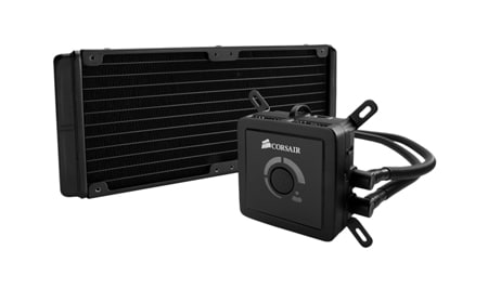
The easy answer is related to the expense and complexity of creating a reliable liquid cooling system. The development of inexpensive liquid cooling has been ongoing for many years and there has recently been a tremendous amount of progress. The applications for desktop computing have now progressed to the point that an enthusiast-class desktop computer (Gaming Rig) is commonly cooled using a maintenance free sealed liquid cooling loop. Dell’s high volume enthusiast desktop division, Alienware, now ships exclusively liquid cooled PC’s to allow for higher CPU clock speeds and as a result, higher performance products to their customers. The workstation and server industry can now leverage the fully developed technology being delivered into that market since manufacturing methods are now well understood and high volume production of these systems have achieved low cost levels with high reliability and high performance through sophisticated microchannel constructs and reliable pumps.
Figure 1: Sealed Liquid Cooling System (Source: Corsair)
In this article, we’ll discuss a rack-based hybrid air/water cooled system built from modular components with considerations for reliability, performance and efficiency.
Before anyone in a datacenter would consider using a hybrid air/liquid cooled server rack, the question of reliability must be answered. One approach is to hard-plumb coldplates with brazed copper tubing. This is expensive and difficult to install. Alternatively, Fluorinated Ethylene Propylene (FEP) tubing can be used. Originally developed in the 80’s for automotive applications, FEP is flexible, tough, has a very low water vapor transmission loss, handles high pressure (see Table 1) and can be reliably joined using cold insertion on a validated triple barb geometry5. In the past 3 years, CoolIT has put well over 2 million tubing joins in the field and experienced zero failures of the cold insertion seal. This type of tubing is not inexpensive but requires no brazing furnace or pre-forming process, which makes for an efficient manufacturing process. Even though the server coolant loop is designed to operate at low pressure (under 42 kPa) the component requirement is to be leak free defined as 276 kPa with a hydrogen trace gas loss rate of less than 7.6E-05 standard cc/s.
| FEP Corrugated Tubing Characteristics – 6mm ID | |
| Maximum Pressure | 380 psi @ 25°C, 180 psi @ 80°C |
| Water Vapor Transmission Rate | 2 g/m/year @ 60°C, 5 g/m/year @ 60°C |
| MIT Flex life ASTM D 2176 | 250,000 cycles |
| Melting point | 250-260°C |
| Tensile Strength | 4,641 psi |
| Safety | UL94-V0 |
Table 1: Characteristics of Fluorinated Ethylene Propylene Tubing
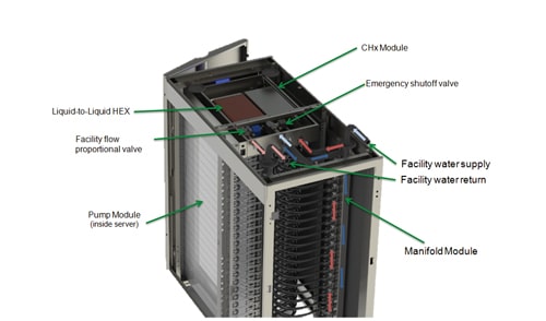
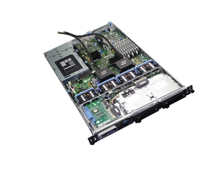
The next question to be addressed is redundancy of circulating pumps. With any liquid cooling the heart of the system is the pump, for if the pump stops, so too does your thermal management. Therefore, a requirement of redundant pumps is necessary. An overview of the rack-based liquid cooling system is shown in Figure 2. One of the novel features of this set-up is the distributed pumping architecture that positions a low power (1.2 – 3.4W), small-form-factor pump on each CPU coldplate. Through the nature of this system and the assumption that there will be at least 2 CPU’s per server (Figure 3), by connecting the CPU modules in series with a “Fail Open” architecture there is always pump redundancy in place. The field reliability of this pump motor for the past 4 years is less than 0.01% failure rate over and by having two in series, statistically, there is a 1 in 100,000,000 chance of a server cooling failure due to pumps.
The Coolant Heat Exchanger (CHx) houses a reservoir, a Liquid-to-Liquid heat exchanger, a proportional valve, an emergency shut-off valve and a control system. The design was created to utilize facility water that recirculates through a simple dry cooler located outside the building. The facility water supply and drain can be fully isolated at the rack level through shut-off valves. The design ensures that there is no mixing of facility water and server coolant such that high purity of the coolant can be maintained to avoid risk of the microchannel coldplates being contaminated by debris or particulate. Depending on the climate, facility water temperatures could range from 40°C down to -25°C or even colder. The proportional valve automatically limits the flow of facility water (or antifreeze mixture) to ensure the coolant going into the servers is always 2 – 3 °C above dew point to avoid any risk of condensation.2 By ensuring the minimum number of moving parts within the CHx (no pumps), the reliability risk of this component is inherently minimized. In the unlikely event of a facility water leak inside the CHx, there has been a network of leak sensors placed within the structure such that if a leak should take place, the facility water supply can be shut down rapidly ensuring that the Rack is isolated from the facility water flow network and does not interfere with the continued operation of the remaining racks. In this emergency situation, the CHx controller is capable of sending out the instruction to safely shut down the servers similar to how a UPS operates in the event of a power loss.
Figure 2: Rack based Direct Contact Liquid Cooling System
One of the concerns for this design was to ensure the flow to be adequate and relatively even in in both standard operation and in the event of a single pump failure inside a server. When a single pump failure condition was simulated, a localized flow reduction of 25% was observed which increased the coldplate thermal resistance from 0.04 °C/W to 0.045 °C/W which maintains a more than adequate level of performance representing less than one degree difference at conventional CPU heat dissipation levels.
Figure 3: 1U server fitted with pump/coldplate modules.
The even flow distribution throughout the fluid network was engineered and validated through the appropriate sizing of the manifolds. The nature of the distributed pumping architecture requires both the cold and warm manifold to have minimal pressure drop. The full system was populated and verified to have no more than 5% variation from the top to the bottom and adequate flow is afforded to each server to maintain performance targets.
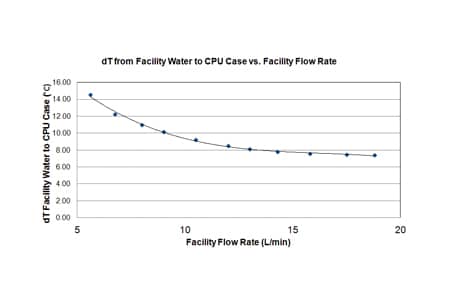
Facility water was supplied at various flow rates while measuring temperatures on the simulated CPU’s. Results are shown in Figure 4. There are many variations for CPU power, CPU loading and server architecture but for the purpose of this test, all simulated CPU’s were loaded with 127W. Assuming that modern CPU’s generally operate with a TCASEMax of 65 – 75°C then the acceptable range of flow rate and temperature for facility water supply can be determined. If the CPU TCASE can’t exceed 65°C and the facility water supply is governed at 5 litres/min, the implied maximum facility water temperature is 50°C. As you would expect, the increased flow of facility water can increase the performance of the CHx. By doubling the facility water flow to 10 litres/min the facility water temperature could be as high as 55°C.
Figure 4: 25U rack test results showing temperature rise from Facility Water vs. Facility Water Flow Rate.
| 25U Rack Power Consumption Data | |
| Pump Power Consumption (40) | 40 x 3.4W = 136W |
| Simulated CPU Heaters (40) | 40 x 127W = 5080W |
| Power supply losses | 1434W |
| Total Power from the wall | 6650W |
Table 2: Power consumption data for liquid cooled 25U server rack test
The power consumption was observed as shown in Table 2, which indicates the cooling system power consumption is approximately 2.6% of the heat that it is transporting. Although beyond the scope of this experiment, the offsetting power reduction of the server fans would likely prove a net reduction of server power consumption even when the pump power is added to the server. In this example the waste heat from the power supply would still need to depend on room cooling. With the elimination of chilling, it is clear that the cooling portion of the total energy consumption can be dramatically reduced without limiting increases in CPU density. The experiment was designed to focus on only cooling CPUs but by increasing the sophistication of the server-cooling loop the system would be capable of absorbing heat generated by RAM, voltage regulators and chipset. The density of a typical air cooled server chassis is 0.04 kW/litre vs. 0.16 kW/litre for hybrid air/water high performance computer node.6 By removing CPU power (and potentially more) from the cooling burden of the datacenter, even dramatic density increases to over 50kW per rack could potentially be supported with high efficiency when combined with “Free Air” cooling methods. By utilizing low cost liquid cooling components and assembly methods, the added expense is estimated to be less than 10% of the cost of the HPC server making the return on investment through realized energy savings, lower capital expenditure through the higher achieved power density and increased compute capabilities very compelling.
References
- Jonathan Koomey. 2011. Growth in Data center electricity use 2005 to 2010. Oakland, CA: Analytics Press. August 1. http://www.analyticspress.com/datacenters.html
- Robert Simons. “Estimating Dew Point Temperature for Water Cooling Applications,” Electronics Cooling, Vol. 14, No. 2, pp. 6-8, May 2008
- Iyengar et al. “Server Liquid Cooling with Chiller-less Data Center Design to Enable Significant Energy Savings,” Proceedings of IEEE Semitherm Symposium, San Jose, 2012
- Iyengar, M., and Schmidt, R., “Energy Consumption of Information Technology Data Centers,” ElectronicsCooling, Vol. 16, No. 4, pp. 28-31, May 2008
- Malone, D., and Valdez, F., “High Performance Tubing for Closed Loop Liquid Cooling Units,” Proceedings of Thermal Management of Electronics Summit, Natick, MA, 2006
- Ellsworth, M., and Iyengar, W., “Energy Efficiency Analyses and Comparison of Air and Water Cooled High Performance Servers,” IPACK2009-89248, July 19-23, San Francisco, CA
Geoff Lyon is the CEO and CTO at CoolIT Systems in Calgary Alberta, Canada where he has been working to develop liquid cooling technologies and products to enable wide-spread adoption in today’s datacom industry. He is a member of IMAPS, an associate member ASHRAE and has presented at Interpack, IEEE Semi-therm, The Server Design Summit and at various other forums. He holds a number of issued and pending patents in the field of liquid cooling and a degree in aerospace engineering from Carleton University.


