Je-Young Chang and Ashish Gupta
Intel Corporation
INTRODUCTION
Integration using multi-chip packaging (MCP) is an effective and popular technology option to increase transistor density in one component by integrating two or more dice or other discrete components on a common substrate. For accurate thermal analyses of MCPs, thermal interactions between active components need to be quantified and understood. These analyses are essential, since the cooling capability of the package may be constrained by the temperature limit of an individual active device in the package.
In this article, a thermal analysis approach is presented for predicting cooling capabilities of MCP architectures. In Figure 1, an example MCP is illustrated with the locations of temperature measurements. For this example, the package has two dice under an integrated heat spreader (IHS), which is cooled by a heat sink. In this configuration, due to the proximity of the two dice, even when an adjacent die is not powered, its junction temperature will be elevated by the power applied to the other die [1-3].

For the above package, the junction temperature of any of the dice is expressed as a function of the power(s) applied to all of the dice:
where Tj,i is the junction temperature of Die “i”; Pi is the power dissipation of Die “i”; Y matrix, also called as “influence” coefficient matrix, is the thermal resistance from the junction to the case; Yca (ºC/W) is case-to-ambient thermal resistance; and Ta is the ambient temperature.
Calculation Processes of Influence Coefficient Matrix
In Equation 1, the Y matrix is based on the principle of linear superposition in conduction heat transfer to calculate the die junction temperatures at an arbitrary combination of powers applied to the dice under steady-state conditions. This can be extended to any number of active dice (N×N matrix) in an MCP. The above equation also applies to a system of multiple components with conduction being the dominant heat transfer mechanism, and provides the first order approximation of the system [1-3]. However, extra caution should be paid to systems with convection and radiation heat transfer wherein the non-linear characteristics introduced through these heat transfer modes cannot be neglected. In the above equation, Yca and Ta values are known at a given design condition, but N×N terms in the influence coefficient matrix must be calculated using the data collected with thermal simulations or experiments.
The general calculation processes of Y matrix are presented below:
Step 1: Select N different power scenarios for N active dice in the MCP. For the current example MCP shown in Figure 1, two different power scenarios, (P1’, P2’) and (P1’’, P2’’), are assumed. These power scenarios should be defined for the power ranges of interest in MCP applications. Typically, it is recommended to apply the power ranges within 10-20% of TDP value of each die in order to minimize the calculation errors due to highly non-uniform heat sources (hot spots) of the power distribution of the die, which cause non-linear spreading patterns while interacting with the power distribution of the neighboring die.
Step 2: Calculate or measure Tj,i values at two (N cases) different power scenarios as defined above using thermal simulations or experiments.
Step 3: Typically, junction temperature differences from the reference point (e.g., DTj,i = Tj,i – Tc) are considered in actual calculations, while the downstream variables (i.e., Yca, Ta) are assumed constant. In this case, all the calculation results (i.e., DTj,i and Pi values) can be summarized as:
Step 4: Rearrange the calculation results for each of DTj,i point, which can be expressed as “power input” matrix:
Step 5: Calculate the values of the elements of the Y matrix using an inverse matrix solver:
Example Calculations
Table 1 shows example temperature data collected with thermal simulations for two different cases of die power scenarios of the MCP package in Figure 1.

For the above data, as discussed in Step 3, the temperature differences and die powers can be summarized as:
The above equations can be rearranged for each of DTj,1 and DTj,2 values, as discussed in Step 4, and “power input” matrix can be expressed as:
In the above equations, the values of Ψ matrix elements can be calculated from an inverse matrix solver, and the complete form of Equation 1 for the MCP package in Figure 1 can be written as:
Graphical Representation of MCP Cooling Envelopes
In Equation 8, there are two linear equations expressed in terms of P1 and P2:
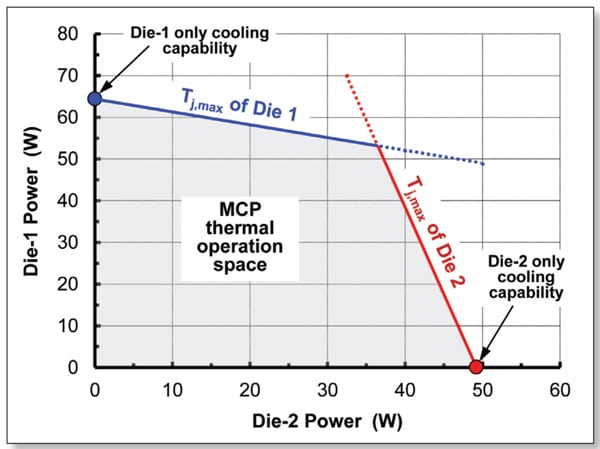
The above two, linear equations can be used to represent cooling capabilities of Die 1 and Die 2 as defined by junction temperature limits and ambient temperature condition. In Figure 2, cooling capability curves of two dice in the MCP in Figure 1 are illustrated. As shown, the solid lines represent the cooling capabilities of Die 1 and Die 2 with respect to junction temperature limits and ambient temperature condition, and the overlapped region (highlighted with gray color) represents thermal operation space of the MCP.

The above graphical representation of the cooling envelope of the MCP is useful to estimate thermal operation spaces for different design conditions, such as different junction temperature limits, ambient temperatures and heat sink designs. It should be noted that, for accurate estimation of thermal operation space, the Y matrix should be re-calculated if there is any significant change in:
- Design conditions, such as die dimensions, die locations, die-to-die spacing, IHS dimensions, etc.
- Material conductivities, such as thermal interface conductivity.
- Die non-uniform heating powermaps.
REFERENCES
[1] Lall, B., Guenin, B., and Molnar, R, “Methodology for Thermal Evaluation of Multichip Modules,” IEEE Trans. CPMT, Vol. 18, No. 4, pp. 758-764, 1995.
[2] Zahn, B., ”Steady State Thermal Characterization of Multiple Output Devices Using Linear Superposition Theory and a Non-Linear Matrix Multiplier,” Proceedings of 14th SEMI-THERM Conference, pp. 39-46, 1998.
[3] Guenin, B., “So many Chips, So Little Time; Device Temperature Prediction in Multi-Chip Packages,” Electronics Cooling, Vol. 12, No. 3, August 2006.


