Jeff Hershberger, Robert Smythe, Xiaoyi Gu and Richard F. Hill
Laird Technologies, Inc.
INTRODUCTION
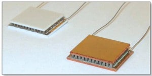
Thermoelectric cooling is an active thermal management technique. A thermoelectric cooler (TEC) has two circuit boards which are typically Al2O3 plates with copper circuit traces attached to them and semiconductor elements soldered between them. TECs are now available where these Al2O3-based circuit boards have been replaced with Thermally Conductive Printed Circuit Boards (TCPCBs). TCPCBs are laminates consisting of a metal backing plate (in this study, 0.64mm thick copper), a layer of thermally conductive filled polymer for electrical isolation, and a copper foil that can be etched into circuit patterns using standard PCB processes. The thermally conductive filled polymer consists of a fully cured epoxy and a high volume loading of different sizes of ceramic particles such as Al2O3. Figure 1 is a photograph of the two types of TECs compared in this study [1].
In a TEC with a concentrated heat load, i.e. one smaller than the TEC, the semiconductor elements far from the heat load still consume electrical power but contribute less heat pumping, leading to reduced efficiency [2]. This occurs because the aluminum oxide circuit boards are thin (< 1 mm) and have limited thermal conductivity (~30 W/mK) and therefore offer limited heat spreading. Thicker aluminum oxide circuit boards would provide better heat spreading but would have higher through-thickness thermal resistance. In some applications, additional heat spreading is provided by the inclusion of a metal or ceramic plate between the heat load and the TEC, but this added component increases cost and complexity and makes quality control more difficult. The use of TCPCBs in TECs seeks to provide heat spreading without these drawbacks by decoupling the through-thickness thermal resistance from the in-plane heat spreading. In this paper, we demonstrate that TCPCB-based TECs provide better efficiency than Al2O3-based TECs when cooling concentrated heat loads.
Experiment
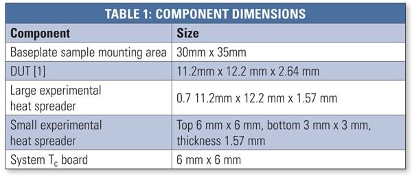
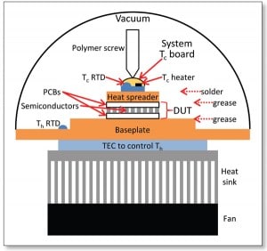
Measurements of coefficient of performance (COP) were performed using a DX8020 TEC Expert system manufactured by RMT Ltd [3]. A schematic of this system is shown in Figure 2 and the dimensions of relevant components are given in Table 1. This system provided a controlled temperature for the hot side of the TEC, variable current and measurement of voltage to the TEC, variable heat load to the controlled side of the TEC, and measurement of the temperature of the controlled side of the TEC, in a vacuum environment at ~1.3*10-2 Pa (~10-4 Torr). The system also provided automatic corrections for heat flow in and out of the controlled side of the TEC by radiation and conduction through the wires. We added a mechanism to press the components down onto the baseplate and the system did not provide corrections for conduction through this structure. We have attempted to minimize that uncorrected heat flow by constructing the mechanism out of a polymer screw sharpened to a point. In this work, the heat load was delivered to the controlled side of the TEC through one of two experimental heat spreaders. A small experimental heat spreader with a trapezoidal cross section was used to simulate a concentrated heat load ~25% the width of the TEC, while a large experimental heat spreader (the same size as the TEC) was used to simulate uniform heat loads. The size of the small experimental heat spreader was chosen to be comparable to the sizes of common heat-producing components such as laser diodes.
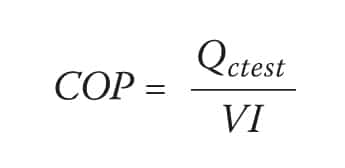
To compare COPs from different TECs and configurations, we used the same heat load Qctest, cold side temperature Tc, and hot side temperature Th in all tests. We chose Th = 25ºC and DeltaT = Th – Tc = 30ºC arbitrarily, and then chose a heat load Qctest = 1.784 W which is equal to 80% of the maximum value typically achievable under those conditions. The TEC leads were soldered to the system’s control board, it was mounted on the baseplate using thermal grease, the experimental heat spreader was mounted on top of it using thermal grease, and the system was evacuated. At the chosen values of Th, DeltaT, and Qctest, the TEC drive current I and voltage V were recorded. The COP was then calculated as follows [4]:
RESULTS AND DISCUSSION
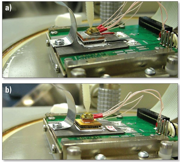
The COP was measured for four different configurations in this work. The small experimental heat spreader was installed in the test system and this concentrated heat load configuration was used to test five Al2O3-based TECs and five TCPCB-based TECs. Then the large experimental heat spreader was installed in the system and this uniform heat load configuration was used to retest the same ten TECs. See Figure 3 for photographs of two of these configurations. The average COP, TEC current, and TEC voltage results are listed in Table 2.
Results Under Uniform Heat Loading
As expected, in both cases with uniform heat loading, the TEC circuit was more efficient (higher COP) than in the cases with concentrated heat load. The difference in COP between the Al2O3-based TECs and TCPCB-based TECs under uniform heat loading was within the listed standard deviations, implying that the two types of TECs perform equivalently under uniform heat loading. This is consistent with the two types of TECs containing the same number and size of semiconductor elements.
Results Under Concentrated Heat Loading
Concentrated heat loading resulted in lower efficiencies for both types of TECs. The fact that the lowest COP resulted from the Al2O3-based TECs under concentrated heat loading implied that the non-uniformity of heat pumping within the TEC circuit was most severe in that case. In comparison, the COP of the TCPCB-based TECs was 87% higher than that of the Al2O3-based TECs under concentrated heat loading. This reduced power consumption implied that the TCPCB had a significant heat spreading effect.
CONCLUSION
Concentrated heat loads on the controlled side of a thermoelectric cooler have been demonstrated to reduce the efficiency of the system in maintaining a desired temperature. The efficiency of a system with concentrated heat loads was shown to be improved when a thermoelectric cooler based on thermally conductive printed circuit boards was used instead of a traditional thermoelectric cooler based on aluminum oxide printed circuit boards.
REFERENCES
[1]The TECs were Laird part numbers OT20,66,F0,1211 (left) and OT20,66,F0T,1211 (right).
[2]Harvey, R. D., Walker, D. G., and Frampton, K. D., “Enhancing Performance of Thermoelectric Coolers Through the Application of Distributed Control,” IEEE Transactions on Components and Packaging Technologies 30(2), 330-336 (2007).
[3]RMT Ltd., “TEC Expert”, <http://www.rmtltd.ru/products/devices/testers/tecexpert/> (accessed 25 March 2014)
[4]Rowe, D. M., [Thermoelectrics Handbook: Macro to Nano], Taylor & Francis, Boca Raton, 1-6 (2006).

