Introduction
Established heatsink manufacturing processes such as extrusion, casting and milling constrain the achievable topology and geometry of the heatsink. The advent of metallic 3D printing (additive manufacture) processes such as selective laser melting (SLM) may remove many of these constraints, forcing the designer to reconsider the approach taken to determine a thermally-efficient heatsink design.
Classic heatsink design involves considering a parametrically specified heatsink topology then optimising those parameters to meet thermal, weight and cost constraints. Those parameters for example might be base thickness, number of fins, fin thickness, fin spacing, fin height. In many ways it is the manufacturing process that dictates those parameters and by how much they can vary. So, how might a heatsink design process be performed if those constraints are no longer imposed?
An additive design methodology has been developed by the Authors that allows a non-parametric topology of the heatsink to be identified as part of an iterative simulation-based process. At its heart, the additive design methodology involves inspection of the performance of an initial design, a determination of where that design should be minimally modified. The modification is then made, and the performance re-evaluated. This process is repeated until a design criterion is met.
This is a subset of a methodology that would entail a minimal improvement made at every possible location, the most advantageous improvement implemented and the process repeated. This in turn is a subset of a methodology that would entail every possible topology being simulated and the best one identified. The present approach aims to be tractable in terms of (simulation) time whilst still having the flexibility to identify an application-specific topology, and is an application of Bejan’s Constructal Law [1], which states
“For a finite-size system to persist in time (to live), it must evolve in such a way that it provides easier access to the imposed currents that flow through it”
Such a law can be said to underpin the formation of many systems both animate and inanimate, including, but not limited to, the branching nature of lightning, rivers, lungs and trees. Various studies based on the Constructal law have focused on ‘volume to point’ (VP) flow systems: thermal conduction of heat [2], liquid flow in a porous media [3] and air flow in lungs [4].
Heatsink behaviour is also a VP problem, though taken as a volume of ‘cold’ used quench a point (rather a small area) heat source. It is not surprising that there are analogies between heatsinks and, say, trees. The heatsink base, like the tree trunk, enables that which is to flow (heat in a heatsink, liquid in a tree) to pass to the area extending portion of it. The heatsink fins, like branches and leaves of a tree, then transfer what is flowing out to their ambient.
The Constructal law can be seen in action in the organic growth exhibited by the additive design methodology reported in this article, which is abstracted from Reference 5.
Application to a Forced Convection Cooling Environment
When applied to heatsink design the additive design process starts by considering the thermal performance of a thin section of heatsink base placed on a heat source, a key from which the heatsink geometry may evolve. This initial geometry is simulated in a cooling environment and the maximum surface temperature location identified. It is postulated that an improvement in the thermal performance of the heatsink can be achieved by increasing the surface area at the point of highest temperature. To achieve this, an additional piece of heatsink material geometry is added to the heatsink, on that face, and the modified heatsink geometry re-simulated. For this study a forced convection cooling environment is used and a 1mmx1mm full length rib is chosen as the additive geometric shape. The first 5 steps in the additive design process are shown in Figure 1. The heatsink design space is 100mm x 100mm x 50mm. There is allowance for 25mm of bypass on the top and the two sides of the heatsink. The initial heatsink base geometry fills the design space in the flow direction, covers the heat 30mm x 30mm heat source in the spanwise direction, is 1mm thick and has a thermal conductivity of 205 W/mK. The inflow is set to 3m/s with an ambient pressure condition at the outlet.
Figure 1 Initial Steps of the Additive Design Process
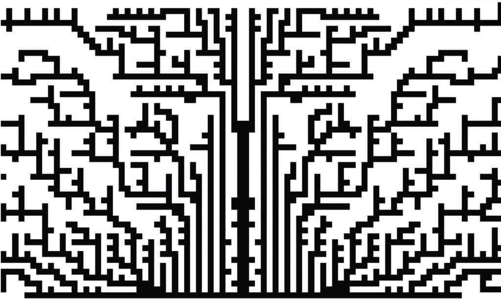
There is no guarantee that the addition of geometry at the hottest point will always cause a decrease in heatsink thermal resistance. If a geometry addition is made that causes an increase in thermal resistance then that added geometry is removed and the location marked so as not to be considered again during the growth process. The growth process concludes when the heatsink has grown to fill a defined design volume and there are no locations left to extend the geometry so as to improve the thermal performance. We define this as the first ‘year’ of growth. A front view of the geometry after this first year of growth is shown in figure 2. Note that symmetry was assumed for the CFD simulations.
Figure 2 Heatsink Profile After 1 ‘Year’ of Growth
A subsequent second year of growth was allowed by resetting all those geometry addition locations that had caused an increase in the thermal resistance of the heatsink during the first year. Some of those locations of area extending that had proved to be detrimental initially, proved to be highly advantageous in this second year of growth. Specifically closer to the heat source where the second year of growth saw a thickening of the base so as to facilitate the flow of heat to the now large surface area (but thin cross section) branched fins.
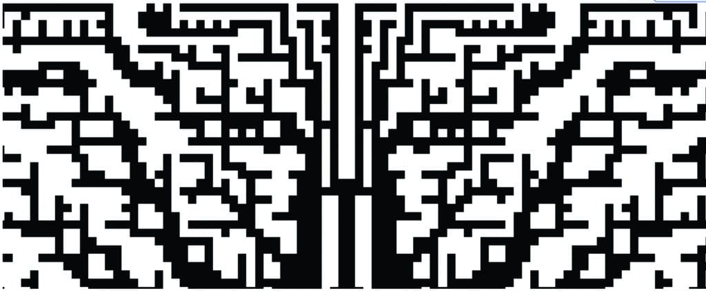
This resetting and continued growth was repeated for a third ’year’, after which no subsequent year of growth provided any further improvement in thermal performance and the additive design process was ended. The final heatsink topology is shown in Figure 3.
Figure 3 Forced Convection Heatsink Profile After Three ‘Years’ of Growth
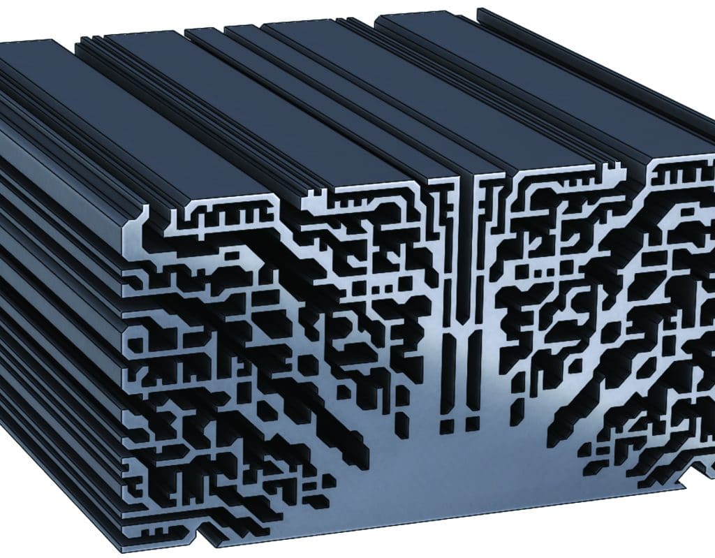
An evident deficiency of the use of a square section rod to grow the geometry is that any angled or curved topological features that manifest will have stair-stepped edges. Although it could beargued this might increase heat transfer, it may be offset by the increase in surface friction. A smoothing stage is therefore conducted where the stepped angled sections are (manually) chamfered (Figure 4). This results in a slight (1.8%) improvement inthermal performance.
Figure 4 Final Chamfered Additively Designed Forced Convection Heatsink
Comparison to Parametrically Defined Heatsink Profiles
It was neither the intention nor the outcome of this study to demonstrate a superior thermal performance of an additively designed heatsink compared to more classic heatsink topologies. However, to put the thermal performance of the additively designed heatsink into perspective, it is compared to two other heatsinks with parametrically definable topologies.
A standard extrusion will have manufacturing constraints such as the maximum aspect ratio of each fin (and similarly fin gap) and minimum fin width. A maximum fin aspect ratio of 10:1 and a minimum fin thickness of 1mm were constraints set in an optimization study of a standard extrusion. Base thickness, number of fins, fin thickness and fin height were set as design variants. A design of experiments was used to populate the design space followed by a gradient based sequential optimisation approach to identify a thermal resistance cost function minima [6].
The same optimization approach was adopted for a heatsink profile that did not have the fin aspect ratio constraint imposed. The fin thickness however was set fixed at 1mm to ensure a valid comparison with the 1mm minimum feature size in the additively designed heatsink.
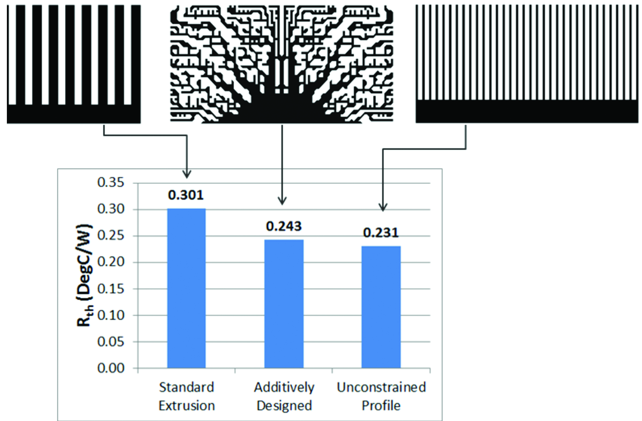
Comparison of the thermal performance of all 3 heatsinks is shown in Figure 5.
Figure 5 Comparison with Parametrically Defined Heatsink Profiles
The additively designed heatsink ‘held its own’, with a thermal resistance less than 5% greater than a parametrically defined profile whose topology is tailored but bound to such unidirectional forced convection environments. Pressure drops for the standard extrusion, unconstrained profile, and additively designed heatsink are 6.9Pa, 7.2Pa and 8.9Pa respectively.
Although both the thermal resistance and pressure drop are slightly worse than the classic heatsink with an unconstrained profile, the strength of the additive approach is its adaptability to complex shaped design volumes and to situations where the heat source is non-uniform due to power or layout variations, where taking a parametric approach might over constrain the design.
Future Work
Instead of using surface temperature as an indicator of where the heatsink would benefit from an area extension, other simulated parameters could be chosen instead. For example the maximum thermal BottleNeck number [7] indicates where there is a lot of heat flow and where the heat is finding it difficult to flow, i.e. where it is bursting to get out. Use of this parameter to determine where best to incrementally grow the heatsink might result in topologies with better overall thermal performance.
Also, the additive design methodology need not be constrained to 2D profiles. The choice of the additive rib geometry was artificial in that it imposed a 2D extruded type profile. The same ‘evaluate and add geometry’ process could be applied using a cuboidal additive geometry smaller than the design space it is attempting to fill so that it has faces that may be hottest in any one of 5 directions, allowing the heatsink geometry to evolve not just up/down/left/right, but also forwards and backwards. This would allow much more complex geometries and potentially superior thermal performances to be achieved.
Conclusions
An additive design methodology has been investigated, applied to a forced convection cooled heatsink design. It has been shown that the resulting thermal performance of the additively designed heatsink topology is within 5% of that of a parametrically optimised defined base/fin type.
Generally this methodology could be applied to other design challenges that:
- Can be quantified in terms of a location that exhibits a behavioural condition indicative of the performance to be optimised.
- Can be geometrically evolved (grown) using an additive geometry shape that has the intention of improving that performance metric.
References:
- Bejan, Adrian (1997). “Advanced Engineering Thermodynamics,” (2nd ed.). New York: Wiley
- Bejan, A., 1997, Constructal-Theory Network of Conducting Paths for Cooling a Heat Generating Volume, International Journal of Heat and Mass Transfer, Vol. 40, No. 4, pp. 799-816
- Errera, M. R., Bejan, A., 1998, Deterministic Tree Networks for River Drainage Basin, Fractals, Vol. 6, No. 3, pp. 245-261
- Reis, A. H.; Miguel, A. F.; Aydin, M., 2004. Constructal theory of flow architecture of the lungs. Medical Physics Vol 31 No. 5, pp. 1135-1140
- Bornoff, R. and Parry, J. (2015) “An Additive Design Heatsink Topology Identification and Optimisation Methodology”. Proceedings of SEMI-THERM Conference, San Jose CA, March 2015
- Parry, J., Bornoff, R., Stehouwer, P., Driessen, L & Stinstra, E. (2003) “Simulation-Based Design Optimisation Methodologies Applied to CFD”, Proceedings of 19th SEMI-THERM Symposium, San Jose CA, March 2003, pp. 8-13
- Bornoff, R. & Blackmore, B. (2010) “thermal bottlenecks and shortcut opportunities; innovations in electronics thermal design simulation.” Electronics Cooling Magazine, Tech Brief, Sept. 2010


