Dirk Schweitzer, Infineon Technologies AG, Am Campeon 1-12, 85579 Neubiberg, Germany
dirk.schweitzer@infineon.com
Introduction
To accurately compute the thermal resistance of a layered structure, such as the Junction-to-Case thermal resistance of a power semiconductor, the heat spreading inside the structure has to be considered. The calculation of the spreading resistance is not a trivial problem [1] and analytical solutions exist only for extremely simple geometries. Using Finite Element Analysis (FEA) the heat spreading and resulting temperature distribution can be accurately computed. But for a quick and simple analysis of the spreading resistance the thermal engineer has to resort to rules of thumb such as the 45° spreading angle [2, 3], or to approximation formulas which can be found in literature [1, 4]. This article presents an alternative approach, namely the concept of the effective heat spreading angle [5].
Effective Heat Spreading Profile
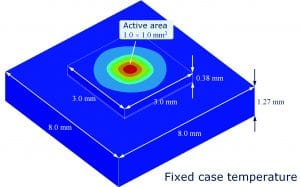
To explain this concept we consider a silicon chip on a copper (Cu) leadframe as shown in figure 1. A power of PH = 10 W is dissipated homogeneously on an active area of 1.01.0 mm2 on the 3.03.0 mm2 chip whereas the bottom temperature of the leadframe is kept constant (ideal cooling).
Figure 1: Silicon chip on Cu leadframe (solder die attach)
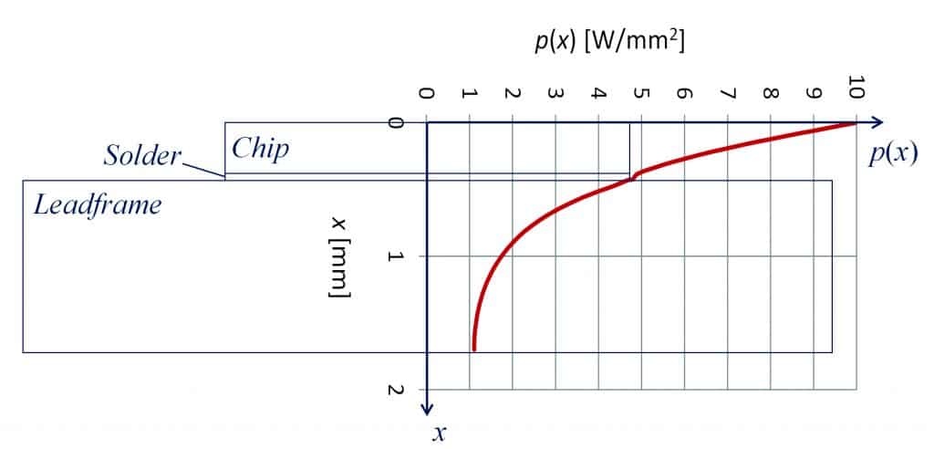
Monitoring the local heat flux density p(x) from the center of the die surface to the center of the bottom surface (x being the distance from the heat source), Figure 2, we notice that the heat flux density drops continuously from initially 10 W/mm2 to about 1 W/mm2 at the bottom. Obviously the heat spreading is the reason for the decreasing heat flux density. If the cross sectional area of the heat flow path was constant the heat flux density would also remain constant throughout the structure. Since the variation of the heat flux density is closely related to the amount of heat spreading the obvious idea was to derive a measure for the spreading angle from the derivative dp/dx of the heat flux density.
Figure 2: Heat flux density along heat flow path
For simplification we shall assume that the heat flux is homogenously distributed over each cross section A(x) of the heat flow path (which is not the case in reality). At each position x the product of cross-sectional area A(x) and heat flux density p(x) equals the total power dissipation PH.
Furthermore we shall assume that the shape of the heat flow cross section does not change as the heat propagates (which is not true either); i.e.: in this case it remains a square area independent of the distance x from the chip surface. For the half side length y(x) of this square we obtain:
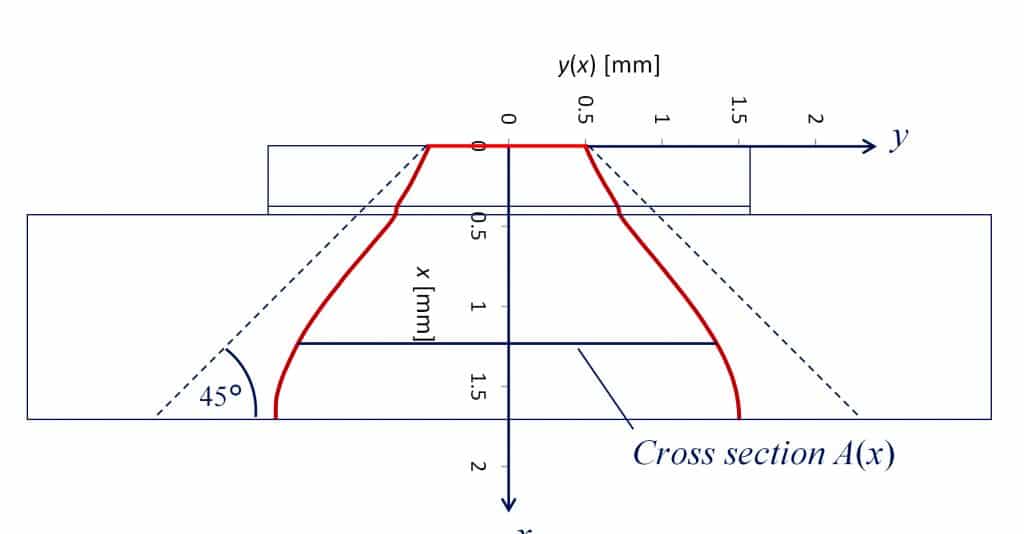
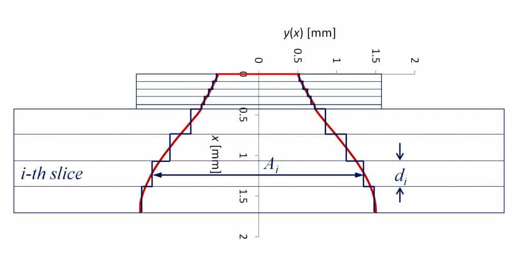
Plotting y(x) vs. distance x we obtain the effective heat spreading profile (figure 3). We call this the effective heat spreading profile as opposed to the real spreading profile because it has been derived for above non-true assumptions. This approach is justified by the fact that we can use the effective heat spreading profile to calculate the spreading resistance within any desired accuracy. Figure 4 shows a discretization of the effective spreading cone. In this example chip and leadframe are each subdivided into 4 slices and the die attach is represented by one more slice. The temperature drop Ti across each slice can be calculated from the density pi of the heat flux passing through it, its thickness di, and its thermal conductivityi :
Because the cross sectional area Ai of each slice has been constructed such that Ai = PH/pi we have:
where θi represents the thermal resistance of the i-th slice such that if we multiply it by the total heat flux PH we obtain the correct temperature difference across that slice. Therefore the sum over all slices
approximates (and for n exactly returns) the thermal resistance of the structure. In practice even a rather coarse discretization of the effective heat spreading profile as in figure 4 results in a quite good approximation of the actual thermal resistance (<1% error in this case). Application of the popular 45° heat spreading assumption on the other hand would overestimate the size of the spreading cone and thus result in a too low value for the thermal resistance (figure 3).
Figure 3: Effective heat spreading profile
Figure 4: Discretization of the effective heat spreading cone
Effective Heat Spreading Angle
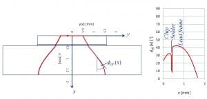
Based on the effective heat spreading profile y(x) the corresponding effective spreading angle can be easily computed (figure 5):
Using Equation (2) we obtain for the heat spreading cone with square cross section:
Figure 5: Effective heat spreading angle
Benefits of the effective heat spreading concept
The attentive reader will now object: That is all well and good but how do I know the heat flux density p(x) along the heat flow path which is required to calculate the effective spreading profile? Which is a valid objection since p(x) can only be obtained by Finite Element (FE) simulation. There would be little motivation to perform a FE simulation to calculate the heat flux density since we could as well use the FE simulation to directly compute the temperature difference and thermal resistance between junction and case.
In the Author’s view the effective heat spreading concept serves two purposes. On the one hand it provides a clear definition of heat spreading cone and spreading angle which so far is often based on a somewhat vague idea of how the heat is spread inside a structure. Heat spreading cone and angle can be visualized which helps us to gain insight into spreading mechanism and influencing factors. Looking at figure 3 we see e.g. that the popular assumption of a 45° spreading angle is overly optimistic in that case. This is the educational aspect.
On the other hand the effective heat spreading concept also serves a practical purpose. As shown in [5] we can often find generally applicable rules for the effective spreading angle which are valid not only for one particular case/device but provide a good approximation for a whole sub-class of cases (e.g. all power semiconductors with solder die attach). Based on these rules and Equation (5) we can implement more accurate spreadsheet calculators for the thermal resistance of this sub-class of devices.
Final remark
We could also try to define the spreading cone by a surface that intersects all isothermals at 90° angle thus ensuring zero heat flux across that border. But contrary to the approach presented above the resulting heat spreading cone would be useless when it comes to computing the associated thermal resistance since the heat flow density over parallel cross sections of the spreading cone is not constant.
References
1. Clemens J.M. Lasance, “Heat Spreading – Not a trivial Problem”, Electronics Cooling, Vol. 14, No. 2, May 2008.
2. Bruce Guenin, “The 45° Heat Spreading Angle – An Urban Legend?”, Electronics Cooling, Vol. 9, No. 4, Nov. 2003.
3. Yasushi Koito, Shoryu Okamoto, and Toshio Tomimura, “Two dimensional numerical investigation on applicability of 45° heat spreading angle”, Journal of Electronics Cooling and Thermal Control, Vol. 4, pp. 1-11, 2014.
4. Seaho Song, Seri Lee, and Van Au, “Closed-Form Equations for Thermal Constriction/Spreading Resistances with Variable Resistance Boundary Condition,” IEPS Conference, pp. 111-121, 1994.
5. Dirk Schweitzer and Liu Chen, “Heat Spreading Revisited – Effective Heat Spreading Angle”, Proc. 31th SEMITHERM, San Jose, pp. 88-94, 2015.

