The packaging and thermal management of electronic equipment has become an important issue because of increased power levels and the simultaneous miniaturization of the devices. With the advent of denser device packaging and faster intrinsic speeds, cost, reliability and size have been improved, but, unfortunately, packaging and thermal management have not followed at the same speed. As a result, it may be difficult to use the latest technology available (microprocessors for example) in avionics.
In the coming years, the electronics industry faces significant thermal management problems in the use of both existing and emerging highly integrated electronic components and modules. The heat removal capabilities of existing cooling techniques are being overtaken in three different areas:
- Increased card or module total heat dissipation (heat power levels higher than 100 W)
- Increased local heat densities for highly integrated components (heat fluxes > 10 W/cm2)
- Maximum use of low-cost plastic components even in the severe avionics applications
These objectives, up to twice as high as the current practices, are associated with size limitations and high reliability requirements. The typical cooling techniques for avionics are based on cooling with conduction and forced or natural convection. These techniques will be inadequate to solve the aforementioned problems, particularly for localized hot spots.
Existing Cooling Techniques
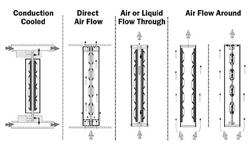
Figure 1. Existing cooling techniques.Two main principles, schematically depicted in Figure 1, are implemented to cool the components on a PC board:
1. The heat load generated by the components dissipation is directly transferred from the components and the board to a cooling fluid according to various thermal transfer modes, namely, radiation and free convection in the air, and forced convection with the air.
2. The heat load is conducted from the components to the board, then from the board to a heat exchanger where they are rejected to a fluid. In this case, the exchanger can be secured at the board ends or directly onto the entire rear face of the board. To minimize the board’s thermal resistance, the board can be fitted with a thermal drain heat pipe. Another alternative is to transfer the heat from the components via high thermal conductivity materials to the module shell and then to a gas or liquid coolant via the heat exchanger surface. On the board itself, the thermal transfer mode is conduction.
Of all these techniques, the most widespread is direct air cooling. Air is available on most platforms, it is simple to implement, and it does not require complex and expensive sealing devices.
Future Cooling Techniques
With the increase of heat densities following Moore’s law, we now face tremendous new challenges in which components heat densities are surpassing 10W/cm2. The standard approach using typical ARINC 600 standard conditions (220kg/h/kw and assuming a T of 15oC) are no longer applicable. Within the Thales Avionics Company, European collaboration research programs have been launched on both civil and military sides to cope with these problems. One of the most promising and investigated routes involves phase change and heat pipe techniques.
KHIEPCOOL Project
Carried out within the framework of the European Commission BRITE-EURAM Program, the three-year KHIEPCOOL research project was initiated to develop an alternate and more efficient cooling technique based on integrated phase change systems. In this project, the proposed multidisciplinary technological development has focused on the development of integrated micro heat pipes through the following phases:
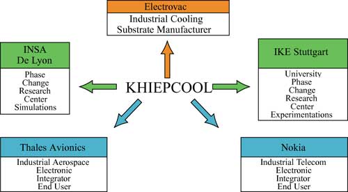
The participants of the project were Sextant Avionique (Currently Thales Avionics) as coordinator, University of Lyon (INSA), University of Stuttgart (IKE), Electrovac, and Nokia. The roles of the participants appear in Figure 2.
Figure 2. Structure of the KHIEPCOOL project.
Heat Pipe Theoretical Study
To design a heat pipe fulfilling the requirements with the associated substrate, simulation studies were performed, thus allowing the evaluation of a great number of configurations and conditions. Using the simulation tool developed by INSA, it was possible to determine the maximum heat transfer capacity and the optimum fill charge of the micro heat pipe. The following parameters were considered: channel geometry (number of corners, corner dimensions and shape, curvature radius of the corner), fluid type and characteristics, wetting angle fluid/wall, channel fill charge, thermal operating conditions (heat flux level, cooling fluid temperature), and heat pipe tilt angle.
For the correct operation of the heat pipe, the capillary pressure difference Pc should be greater than the summation of the liquid pressure losses
Pl, vapor pressure losses
Pv and pressure losses due to the longitudinal
P// and transversal
P| components of the gravity forces:
where Leff is the effective heat pipe length. The maximum capillary pressure occurs when the meniscus curvature has a maximum value at the evaporator end and is nearly zero at the condenser end. In this case, the corresponding heat transfer rate is maximized.The model has been validated with the experimental results obtained by IKE for a micro heat pipe array filled with water. There is a good agreement between the experimental and theoretical results for the micro heat pipe operating with the wick and the corners. It has been shown that the corners transport a larger mass flux rate than the wick. The wick effect is to provide a small capillary radius of the meniscus at the evaporator end and, hence, to ensure a high capillary pumping in the heat pipe. The developed model is a suitable tool for simulating various micro heat pipe configurations under a variety of operating conditions and, so, can be used as a means to select an optimum geometry.
Heat Pipe Structure Design
To minimize the thermal path, a direct linkage of the chips onto the heat pipes structure is foreseen for the most demanding applications. In such conditions, the coefficient of thermal expansion of the heat pipe structure must be as close as possible to that of the chip or substrate structure (Si or Al2O3).
Due to the advantages of metal matrix composite substrates in electronics cooling, an aluminum silicon-carbide (AlSiC) composite was chosen as the base material. Containing a volume fraction of about 75% SiC, AlSiC offers an outstanding set of properties required in high performance packaging. These properties include high thermal conductivity (180-200W/mK), low coefficient of thermal expansion (6-8×10⁻⁶K-1) and low density (3g/cm3).
The composite is manufactured by making a porous preform from silicon carbide powder, which is then infiltrated with molten aluminum via gas pressure. The resultant product is a fully densified homogeneous material including an outer aluminum skin. By following some design rules many structures can be caste net-shape. During this study four different manufacturing routes were considered:
- Casting one composite part with internal heat pipe structures
- Casting two composite parts with heat pipe structures and joining them afterwards
- Casting one composite part and simultaneously integrating the heat pipes
- Casting one composite part and joining with separate heat pipes
For this study the heat pipe manufacturing was done following route 2.
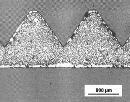
Based on simulations of micro heat pipe arrays, the manufacturability of substrates 120 x 35 x 1.5 mm with axial triangular grooves was demonstrated. These structured plates comprised the base of the flat heat pipe. For prototypes, a grooved geometry with a depth of 1 mm and an opening width of 1.4 mm was chosen (see Figure 3).
Figure 3. Selected structure for heat pipe prototypes.The base plates were coated with an electrolytic nickel layer of 10�m and a 0.3�m gold layer to protect the aluminum skin of the composite from corrosion and to allow soldering. The plated AlSiC parts were reflow soldered using preforms of eutectic Au-Sn solder (melting point 280oC) along the outer rims of the substrates. For the purpose of filling, a tube (2mm outer diameter) made out of an iron-nickel-cobalt alloy (Kovar®) was soldered onto one end of the heat pipe.
Heat Pipe Experimental Study
Two different kinds of experimental investigations were performed (i.e., extensive optical investigations for fluid flow visualization and micro heat pipe design optimization), and more than ten series of performance tests for design evaluation.
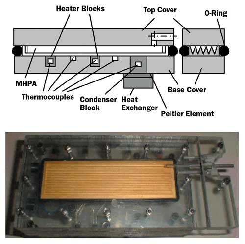
Figure 4. Test module for visualization of internal processes.The test module used for the optical experiments appears in Figure 4. It was a vacuum chamber comprised of two polycarbonate plates (serving as top and base covers) and an O-ring (serving as the surrounding wall). The structured plate was placed into this chamber. The O-ring fit tightly to the structured plate. Heater block temperature was controlled by electrical resistance. The heat sink was cooled by a computer-controlled Peltier element and a water heat exchanger. For measuring the wall temperature, thermocouples were directly attached to the micro heat pipe surface and integrated in the heater and condenser blocks. The fluid flow was investigated by a CCD camera connected to a computer for digital image processing.
It was found that, depending on the investigated structure, more or less strong interaction processes occurred between the individual triangular grooves of the array. In addition, the sharp-angled corners acted like liquid arteries and they supported the proper rewetting of the grooves after a dry-out.
With enhanced wick structures (i.e., triangular grooves plus wicks), a heat transport capacity of over 30W was obtained at a heat pipe thermal resistance of less than 1.0 K/W. For comparison: the overall thermal resistance for a non-filled (working only by thermal conduction) micro heat pipes is about 6.8 K/W.
A further performance improvement is possible. The very latest micro heat pipe design has a heat transport capability well over 40W.
Heat Pipe Integration
Heat pipe integration must be considered according to many parameters, which define the electronic card. Among these parameters are:
- Interconnection substrate
- Component package
- Cooling principle
- Assembly techniques
One must pay close attention to different thermal interface materials, mounting techniques, and heat power levels. The required improvements in the whole system’s thermal performance can be achieved by minimizing thermal resistances between the different system levels. Hence, it is important to carefully evaluate and analyze the entire system and its environment.
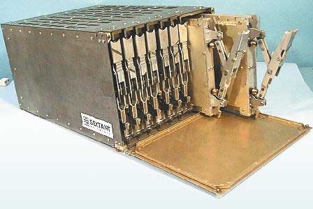
In the case under discussion, the electronic cards were fixed inside rack-mounted line replaceable modules (Figure 5). Each rack contained nine such modules cooled by air convection.
Figure 5. Rack and LRMs configuration.Two technological approaches (conduction cooling and convection cooling) were studied by experimentation and numerical simulation.
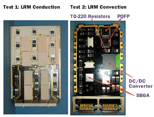
- Conduction cooling – The cards were fixed on an aluminum support into which the heat pipe was integrated. Heat generated by the electronic packages was transferred by conduction to the air cooler via a thermal clamp.
- Convection cooling – The electronic packages were mounted double-sided on the circuit board. Air was blown directly on the components to cool them by forced convection (Figure 6).
Figure 6. Conduction and convection demonstrators.
Test Results
The objectives of these tests were to check the performance of the heat pipe in a manner consistent with the specific aircraft environment and to evaluate the junction temperature benefit on actual configurations:
Static thermal performance versus position
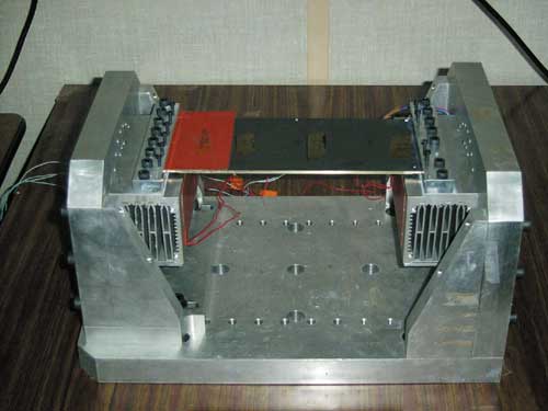
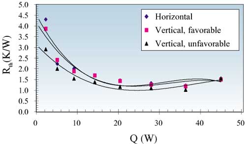
A test setup was developed to clamp the heat pipe at both extremities (Figure 7). The results show a good homogeneity of the heat pipe performance versus tilt angle, as illustrated in Figure 8.
Figure 7. Heat pipe test setup.
Figure 8. Heat pipe thermal resistance dependence on the tilt angle.
Thermal performance under vibration
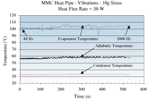
Using the same setup as above mounted on a shaking table, the heat pipe was subjected to a sine wave level of 10G (40 Hz – 2000 Hz) under a heat flux rate of 30 W. The results, as presented in Figure 9, indicate the vibrations had no detrimental effects on the heat pipe.
Figure 9. Temperature variation during vibrations.
Thermal performance under acceleration
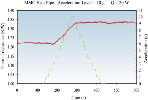
The main identified risk when employing heat pipes in aircraft conditions is the behavior of the heat pipe when subjected to reverse acceleration, which could prevent the liquid from returning to the evaporator section. When studying this, the setup was mounted on a centrifugal machine, as illustrated in Figure 10. The acceleration was varied using the table angular velocity up to 10G. The results in Figure 11 show a variation in the thermal resistance of about 10%, starting at 5G.
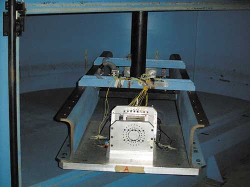
Figure 11. Thermal resistance versus acceleration.
Conclusion
Micro heat pipes have been developed to meet avionics requirements. A mathematical model was developed to simulate the triangular cross section micro heat pipe performance including wicks. The main calculated parameters were the maximum heat transfer rate and the optimum fill charge. From numerous simulations, the authors determined the final heat pipe geometry and established the manufacturing route of the metal matrix composite heat pipe prototypes. They then carried out two different kinds of experimental investigations to determine the micro heat pipe thermal performance:
- Extensive optical investigations for fluid flow visualization
- Micro heat pipe design optimization.
With enhanced wick structures, a heat transport capacity of over 30W could be obtained with a heat pipe thermal resistance of less than 1.0 K/W. The heat transport capability was more than six times higher than that of an aluminum block with the same cross-section. The authors also analyzed assembly technique of heat pipes.
In the application:
- The objectives of 100W dissipation at the card level was reached with 30-40W at the heat pipe level.
- The chips survived the static thermal tests with hot spots densities up to 10W/cm2.
- Dynamic vibrations had no detrimental effects on the heat pipe thermal performance
- Heat pipe depriming began at 5g when subjected to reverse acceleration
- The technology has been considered applicable to avionics, provided that required complementary industrial developments and long term behavior checking occur.

