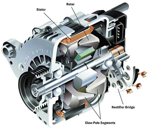
Ever since the advent of the automotive alternator, or claw-pole alternating current generator, in the 1960’s, there has been an ever-increasing thermal design challenge to cool the power electronics in these machines. Figure 1 depicts a typical cutaway section of a modern day alternator. At first glance one may think that cooling the diodes in a rectifier bridge of an alternator would not be a particularly demanding thermal task. On the contrary, it is a very demanding thermal task. Designs today are approaching thermal resistances as low as 0.2oC/W in package sizes of 160 cm3.
 |
Figure 1. Automotive alternator.
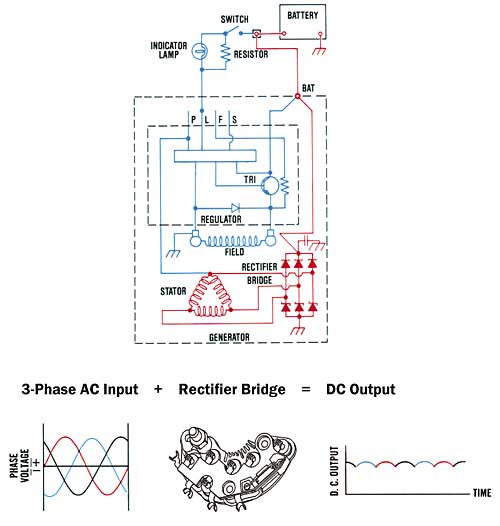
How did this come to be? Prior to the alternator, commutated DC generators provided electrical power. With such a machine, the inherent electrical output from the machine was DC power and therefore there was no need for AC to DC conversion with power electronics. But with increasing electrical power demands, a switch was made to the alternator with its higher output power capability. With the alternator, however, the inherent electrical output from the machine is AC power and it is necessary to convert this into DC power for use on the vehicle. This is accomplished through the use of a rectifier bridge that typically incorporates six semiconductor diodes. (See Figure 2.) Hence, the need exists for electronic cooling in the automotive alternator.
 |
Figure 2. AC to DC power conversion in an alternator.
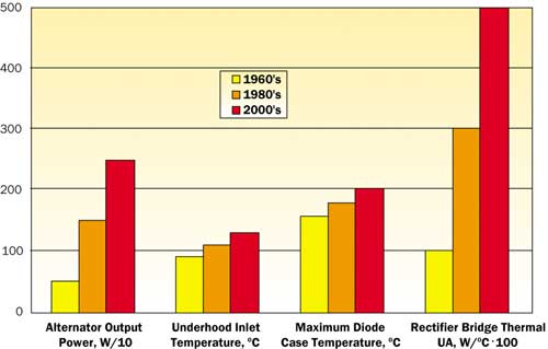
Admittedly, the thermal designs of these early alternators weren’t particularly taxing. Since that time, though, there has been an ever-increasing demand for on-board electrical power from the alternator. When alternators first appeared in the 1960’s, power requirements were typically 500 W. In the 1980’s this power demand escalated to 1500 W. Today, many production alternators are capable of 2000 W and designs are being developed that provide upwards of 3000 W of electrical output power. Accompanying this increase in electrical performance has been a proportional increase in heat loss of the rectifier bridge since its thermal losses are essentially linear with output power.
The thermal challenges have also been compounded by the rise in underhood ambient temperatures in automotive vehicles. In the 1960’s the typical underhood inlet cooling air temperature to the alternator was 90oC. By the 1980’s this had jumped up to 110oC. Today, applications approach the 130oC range.
But the demands on the thermal design don’t stop there. Over the same period of time, there has been increasing worldwide pressure to drive the overall alternator cost down, and the rectifier is not immune to this pressure. Also, the reliability requirements have been increasing. And, for good measure, the package size of the alternator, per unit of electrical output power, continually shrinks and places greater and greater demands on package size. Additionally, there is a continual requirement for lower and lower underhood noise. This has driven the need to minimize the cooling airflow rate and maximize its use. Couple all of these factors together and it is easy to see that electronics cooling in automotive alternators has become a very hot topic.
So, what has been done to meet this challenge? First let us look at the device itself. Early 1960’s vintage rectifiers incorporated diodes that were typically packaged in a can configuration. It had a maximum reliable operating case temperature of roughly 160oC. Later in the 1980’s, button and sandwich configured diodes became popular and with improvements in diode manufacture the temperature capability was raised to 180oC.
Today, the trend among several manufacturers has been to use press-fit diodes with a maximum operating case temperature of 200oC. These temperature improvements were driven primarily by improved package designs that reduced fatigue failures resulting from thermal expansions and contractions in the diode attachment area. Clearly, these improvements in diode temperature capability have greatly helped in meeting this thermal design challenge.
Although there have been significant improvements in the temperature capability and reliability of the diodes, the forward voltage drop and power loss of these devices has remained essentially constant. Therefore the thermal design of the rectifier heat sinking itself has had to match the increases in thermal losses of the rectifier. Figure 3 shows how the overall thermal design, as expressed by the UA product (overall heat transfer coefficient times area, or 1/Rtot), driven by the increasing power demands on the rectifier have escalated through the years to the levels they are at today.
 |
Figure 3. Historical thermal developments in alternators.
Heat sinking designs from the 1960’s incorporated simple stamped heat sinks. The heat sink configurations were essentially best guesses on the part of the engineer with testing to substantiate the design. The rectifier bridge was located on the back surface of the machine, away from the drive pulley. The alternator itself had a large diameter centrifugal fan, located externally on the front of the machine that would pull air across the rectifier bridge. With such an arrangement the large amount of air pulled across the rectifier bridge by the external fan made up for any thermal design weaknesses.
However, the drive toward lower noise led to the dual-internal fan configuration in the 1980’s. With this arrangement, two smaller diameter centrifugal fans were placed on either side of the rotor located within the machine. While breaking up the flow streams within the machine and decreasing the diameter of the fans significantly reduced windage noise, it also reduced the ‘brute force’ cooling potential of the fan. Heat sink designs became more refined and the use of FEA (finite element analysis) techniques emerged. Extruded aluminum heat sinks became common with an emphasis on thin, closely spaced fins to maximize the thermal performance in a given size package.
Today, the extruded heat sink has reverted to a stamped heat sink. The stampings are of fairly large surface area and rely primarily on impingement flow to yield high convection coefficients. During this time the use of CFD (computational fluid dynamics) packages have become more prevalent, as well as further use of FEA.
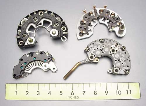
Also, liquid cooling has emerged, both in the US and Europe. With such an approach, the coolant system of the vehicle itself is tapped into and routed through the generator frame to cool the electronics and the various machine components. However, this approach appears to be a niche market and does not present strong growth potential due to the inherent high cost of the alternator and the associated vehicle plumbing to the alternator. Figure 4 displays typical rectifier bridge configurations from various manufacturers.
 |
Figure 4. Typical rectifier bridge configurations.
So what does the future hold? The relatively low cost per unit electrical output power of the claw-pole alternator will ensure its continued use well into the future. Also, the trends presently in place will certainly continue for the foreseeable future; higher electrical power demands, higher inlet cooling air temperatures, smaller package sizes, increased reliability, lower cost, and lower noise. Therefore, the thermal design challenges will not go away, they will only intensify.
To address this, we can expect that all fronts of this thermal battle will be involved. First, expect to see continued refinement of the semiconductor devices themselves. Development is continuing for devices with lower power loss and with higher inherent reliability. Second, expect more inventive ways to provide large total surface areas for convective air cooling in relatively small and low cost packages. And third, look to see more efficient machine designs to minimize the heat loss from the rest of the machine to minimize the thermal interaction with the rectifier bridge. The challenges are formidable and real. But simply put, companies with designs that can meet these challenges will forge ahead, and those that can’t, won’t.


