Modern electronics thermal management faces considerable challenges in the wake of component miniaturization, which has led to higher demands on net heat flux dissipation. With the industry closely following Moore’s Law, the future demands are becoming increasingly more challenging [1]. Two-phase passive devices are proven present day solutions. Conventional heat pipe technology has been successfully applied in the last thirty years for the thermal management of a variety of applications like heat exchangers, economizers, space applications, and electronics cooling, to cite a few [2].
Although a plethora of designs of classical heat pipes are available, recent industry trends have frequently shown the limitations of these conventional designs. This has led to the evolution of novel concepts fitting the needs of present industry demands. A relatively new and emerging technology, Pulsating or Loop-type Heat Pipes (PHP), as proposed by Akachi [3, 4], represent one such field of investigation. This range of devices is projected to meet all present and possibly future specific requirements of the electronics cooling industry, owing to favorable operational characteristics coupled with relatively cheaper costs.
Although grouped as a subclass of the overall family of heat pipes, the subtle complexity of internal thermo-fluidic transport phenomena is quite unique, justifying the need for a completely different research outlook. A comprehensive theory of operation and a reliable database or tools for the design of PHPs according to a given microelectronics-cooling requirement still remain unrealized [5]. Nevertheless, the prospects are too promising to be ignored.
|
|||||||
Construction Details
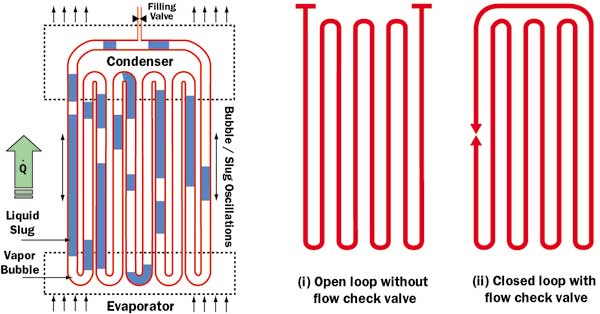
A PHP consists of a plain meandering tube of capillary dimensions with many U-turns (Figure 1a). In contrast to a conventional heat pipe, there is no additional capillary structure inside the tube. There are two ways to arrange the tube: open loop and closed loop. As the names suggest, in a closed loop structure, the tube is joined end-to-end (Figure 1b). The tube is first evacuated and then filled partially with a working fluid, which distributes itself naturally in the form of liquid-vapor plugs and slugs inside the capillary tube. One end of this tube bundle receives heat, transferring it to the other end by a pulsating action of the liquid-vapor/bubble-slug system. There may exist an optional adiabatic zone in between. Also, one or more flow-direction control check valves may be introduced at suitable locations to augment the performance. Figure 2 represents some practical design variations as proposed in [3].
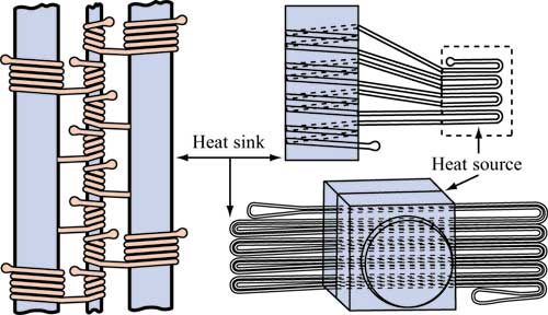 |
Figure 2. Some practical design variations of pulsating heat pipes (adapted from [3]).
Operational Features
A PHP is a complex heat transfer device with a strong thermo-hydraulic coupling governing its performance. It is essentially a non-equilibrium heat transfer device. The performance success of the device primarily depends on the continuous maintenance or sustenance of these non-equilibrium conditions within the system. The liquid and vapor slug transport results because of the pressure pulsations caused in the system. Since these pressure pulsations are fully thermally driven, because of the inherent constructions of the device, there is no external mechanical power source required for the fluid transport.
Consider a case when a PHP is kept isothermal throughout, say at room temperature. In this case, the liquid and vapor phases inside the device must exist in equilibrium at the saturated pressure corresponding to the fixed isothermal temperature. Referring to the pressure-enthalpy diagram, Figure 3, the thermodynamic state of all the liquid plugs, irrespective of their size and position, can be represented by point A. Similarly point B represents the thermodynamic state of all the vapor bubbles present in the PHP.
Suppose the temperature of the entire PHP structure is now quasi-statically increased to a new constant value. Then the system will again come to a new equilibrium temperature and corresponding saturation pressure, point A’ and point B’, in Figure 3. In doing so, there will be some evaporation mass transfer from the liquid until equilibrium is reached again. A similar phenomenon will be observed if the system is quasi-statically cooled to a new equilibrium condition A” and B” (exaggerated representation for clarity) [6].
In an actual working PHP, there exists a temperature gradient between the evaporator and the condenser section. Further, inherent perturbations are always present in real systems as a result of:
- Pressure fluctuations within the evaporator and condenser sections due to the local non uniform heat transfer always expected in real systems.
- Unsymmetrical liquid-vapor distributions causing uneven void fraction in the tubes.
- The presence of an approximately triangular or saw-tooth alternating component of pressure drop superimposed on the average pressure gradient in a capillary slug flow due to the presence of vapor bubbles.
The net effect of all these temperature gradients within the system is to cause non-equilibrium pressure condition which, as stated earlier, is the primary driving force for thermo-fluidic transport. As shown in Figure 3, heating at the evaporator continuously tries to push point A upwards on the liquid saturation line of the pressure-enthalpy diagram. Simultaneously, point B is forced to move downwards on the vapor line at the other end.
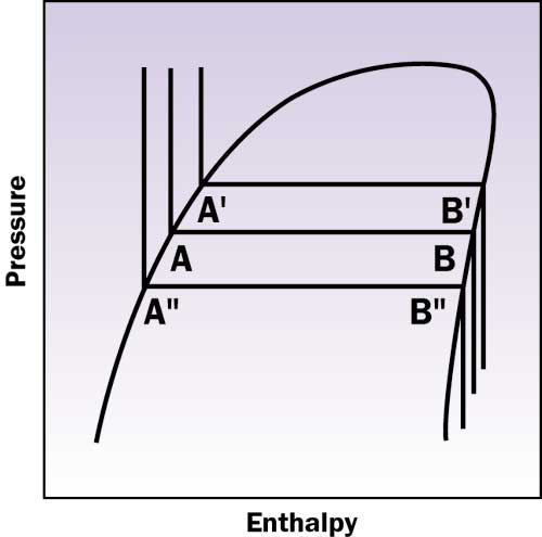 |
Figure 3. Typical pressure-enthalpy diagram.In this way a sustained non-equilibrium state exists between the driving thermal potentials and the natural causality, which tries to equalize the pressure in the system. Thus, a self-sustained thermally driven oscillating flow is obtained in a PHP. Note that no “classical steady state”‘ occurs in PHP operation. Instead pressure waves and pulsations are generated in each of the individual tubes which interact with each other possibly generating secondary and ternary reflections with perturbations.
From a force balance of gravity and surface tension leading to the definition of the E�tv�s number, the theoretical maximum tolerable inner diameter (dcrit) of a PHP capillary tube can be calculated as [3]:
 |
where:
| Bo | = | Bond number = d � (g( |
| d | = | tube internal diameter (m) |
| E� | = | E�tv�s number = (Bo)2 |
| g | = | acceleration due to gravity (m/s2) |
| = | surface tension (N/m) | |
| = | liquid density (kg/m3) | |
| crit | = | critical |
| liq | = | liquid |
| vap | = | vapor |
At diameters below this value, there is a tendency for surface tension forces to predominate, and this assists in formation of stable liquid slugs, an essential prerequisite for PHP operation. In vertical orientation, slug flow is known to exist even at bigger diameters in devices such as a standard bubble pump, depending on the heat flux. In horizontal flow, there exists a greater possibility of flow stratification as the diameter of the tube increases. In the light of these facts, the PHP critical diameter, as suggested above, requires further investigation to be established as a design rule [6].
Design Parameters
Various experimental investigations have been done with the aim of making a parametric study of a PHP [7, 8]. These studies indicate the following main variables affecting PHP performance:
- Geometric Variables: Overall length of the PHP, diameter/size and shape of the tube, length and number of turns of evaporator/condenser/adiabatic section.
- Physical Variables: Quantity of the working fluid (filling ratio), physical properties of the working fluid, tube material.
- Operational Variables: Open loop or closed loop operation, heating and cooling methodology, orientation of the PHP during operation, use of check valves.
It is evident that there are multiple variables which simultaneously affect the operation and performance of PHPs. Further, so far as capillary slug flow exists inside the entire device, it has been demonstrated that latent heat will not play a significant role in the device performance [6, 9]. Nevertheless, bubbles are certainly needed for self-sustained thermally driven oscillations.
On the other hand, under certain operating conditions, flow pattern transition to annular flow may occur. The probability of such an event is high with a combination of a high E�tv�s number, high heat flux, and comparatively low liquid filling ratio ( 50% or lower). Note that if a flow regime changes from slug to annular, the respective roles of the latent and sensible heat transport mechanism may change considerably. This aspect requires further investigation [10].So, the performance not only depends on a large number of parameters described above, but also on the flow pattern. This makes it all the more difficult to undertake mathematical modeling using conventional techniques.
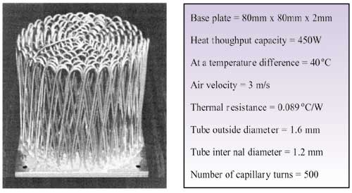 |
Figure 4. A typical ‘Kenzan Fin’ and its performance data (adapted from [3]).
Typical Performance Data
Figure 4 shows a typical pulsating heat pipe, also referred to as “Kenzan Fin” which has been applied for cooling multi-chip modules [3]. The thermal performance data is also included. The advantages of such systems can be summarized as follows:
- Compared to solid metal fins, this type of fin structure is certainly light weight.
- If optimal operation is achieved, this fin structure is thermally an order of magnitude better than equivalent solid fins even with an air cooling option.
- As the tube diameter is reduced, thermal performance of wicked conventional heat pipes is drastically reduced, while there is a parallel increase in manufacturing complexity and cost.
The latter fact is clear from Figure 5, which shows the maximum thermal performance of conventional wicked copper-water heat pipes of internal diameters 3 mm, 2.5 mm and 2.0 mm respectively in vertical orientation [11]. In addition, PHPs have an edge over conventional wicked heat pipes as they are not limited by capillary or entrainment performance limits encountered in conventional heat pipes.
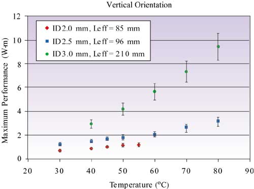 |
Figure 5. Maximum performance of miniature cylindrical copper-water conventional wicked heat pipes.
Conclusions
Pulsating Heat Pipes, apparently simple and very promising cooling devices, are very intriguing for theoretical and experimental investigations alike. They are attractive heat transfer elements, which due to their simple design, cost effectiveness, and excellent thermal performance may find wide applications. Since their invention in the early nineties, they have so far found market niches in electronics equipment cooling. Their complex operational behavior, which is not yet fully understood, has raised an ever growing academic interest. Until now, it has not been possible to simulate the PHP performances and there exists no complete engineering design tools.
References
- Azar, K., “The History of Power Dissipation”, ElectronicsCooling, Vol.6, No.1, January 2000.
- Groll, M. and R�sler, S., “Operation Principles and Performance of Heat Pipes and Closed Two-Phase Thermosyphons”, Journal of Non-Equilibrium Therm., Vol. 17, 1992, pp. 91-151.
- Akachi, H., Pol�svek, F., and Svtulc, P., “Pulsating Heat Pipes”, Proceedings 5th International Heat Pipe Symp., Melbourne, Australia, 1996, pp. 208-217.
- Akachi, H. and Miyazaki, Y., “Stereo-Type Heat Lane Heat Sink”, Proceedings 10th International Heat Pipe Conference, Vol. 3 (Session F), Stuttgart, Germany, 1997, pp. 50-55.
- Khandekar S., Schneider, M., and Groll, M., “Mathematical Modeling of Pulsating Heat Pipes: State of the Art and Future Challenges”, 5th ASME/ISHMT Joint International Heat and Mass Transfer Conference, ISBN 0-07-047443-5, Kolkata, India, 2002, pp. 856-862.
- Groll, M. and Khandekar, S., “Pulsating Heat Pipes: A Challenge and Still Unsolved Problem in Heat Pipe Science”, Proceedings 3rd International Conference on Transport Phenomenon in Multiphase Systems, ISBN 83-88906-03-8, Kielce, Poland, 2002, pp. 35-43 (also in Archives of Thermodynamics, Begell House, ISSN 1231-0956, Vol. 23/4, 2002, pp. 17-28.)
- Tong, B., Wong, T. and Ooi, K., “Closed-Loop Pulsating Heat Pipe”, Applied Thermal Engineering, ISSN 1359-4311, Vol. 21, 2001, pp. 1845-1862.
- Khandekar, S., Groll, M., Charoensawan, P., and Terdtoon, P., “Pulsating Heat Pipes: Thermo-fluidic Characteristics and Comparative Study with Single-Phase Thermosyphon”, Proceedings 12th International Heat Transfer Conference, ISBN-2-84299-307-1, Grenoble, France, 2002, pp. 459-464.
- Shafii, M. B., Faghri, A., and Zhang, Y., “Thermal Modeling of Unlooped and Looped Pulsating Heat Pipes”, ASME Journal Heat Transfer, Vol. 123, 2001, pp. 1159-1172.
- Khandekar, S., and Groll, M., “Understanding Operational Regimes of Pulsating Heat Pipes: An Experimental Study, Applied Thermal Engineering, Elsevier Science, ISSN 1359-4311, Vol. 23/6, pp. 707-719, 2003.
- Khandekar, S., Groll, M., Luckchoura, V., Findl, W., and Zhuang J., “Micro Heat Pipes for Stacked 3D Microelectronic Modules” (accepted for publication), Proceedings InterPack 2003 – International Electronic Packaging Technical Conference, Hawaii, July 2003.

