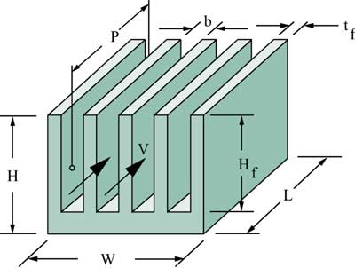
In the last issue of ElectronicsCooling a methodology was presented for estimating parallel plate-fin heat sink thermal resistance [1]. The method presented assumes that the air flow rate is given, either in terms of the average velocity, V, between the fins or a volumetric flow rate, G. Although this methodology was shown to be useful in examining the effects of heat sink geometry on heat sink thermal resistance over a range of air flow rates, it cannot be used by itself to predict the performance of a given heat sink design in a particular application. To do this it is necessary to know the actual air flow rate that will be delivered through the heat sink by the fan or blower to be used in the application. To determine the air flow rate it is necessary to estimate the heat sink pressure drop as a function of flow rate and match it to a curve of fan pressure drop versus flow rate. A method to do this, using equations presented in a paper by Culham and Muzychka [2], will be discussed in this article. As in the previous article, the heat sink geometry and nomenclature used is that shown Figure 1.
 |
Figure 1. Parallel plate fin heat sink configuration.
The pressure drop across the heat sink, ![]() P, is given by
P, is given by
 |
where
L = Length of the heat sink channels in the flow direction
Dh = Hydraulic diameter of the flow channels
![]() = Air density
= Air density
V = Average velocity of air flowing through the channels
The hydraulic diameter, Dh, is approximately equal to 2b where b is the gap between the fins given by
 |
where
Nfin = Number of fins
tf = Fin thickness
W = Heat sink width
The coefficients Kc and Ke represent the pressure losses due to the sudden contraction and expansion of the flow entering and leaving the heat sink flow channels between the fins. These coefficients may be determined using
and
where = ratio of the area of the flow channels to that of the flow approaching the heat sink, and is given by
 |
The average velocity for use in Equation 1 is related to the volumetric air flow rate, G, by
 |
where Hf = fin height
The apparent friction factor, fapp, for hydrodynamically developing laminar flow is related to the friction factor, f, for fully developed flow and may be calculated from
 |
where L* is given by
 |
and the Reynolds number, Re, is given by
 |
where � = dynamic viscosity of air
The friction factor for fully developed laminar flow used in Equation 1 is a function of both the aspect ratio (b/Hf), , of the heat sink flow channels and the Reynolds number as given by
 |
Using the preceding equations and Equation 1 with air velocity in m/s and air density in kg/m3 will give the overall pressure drop across the heat sink in Pascals (1 Pascal = 0.00401 in. of H2O).
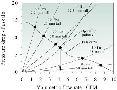
For purposes of illustration, these equations were used to estimate the pressure drop across a heat sink of the same dimensions as that considered in the earlier article. That is a 50 x 50 mm heat sink with 10 to 30 fins, 0.5 mm thick and ranging in height from 12.5 to 50 mm. The pressure drop for each heat sink configuration was calculated for volumetric air flow rates ranging from 0 to 10 CFM (0.00472 m3/s). These results are shown in Figure 2.
 |
Figure 2. Heat sink pressure drop curves and fan curve with flow operating points.
At a given volumetric air flow rate those heat sinks with more fins and shorter fins experience a higher air velocity in the heat sink channels and exhibit a higher pressure drop. At the same volumetric air flow rate those with fewer fins and taller fins experience a lower air velocity in the heat sink channels and exhibit a lower pressure drop. Also shown in Figure 2 is the fan curve for a typical fan that might be used to provide air flow for the heat sinks under consideration. The intersection of the fan curve with the flow impedance curve for any heat sink determines the flow the fan will deliver to that heat sink. As may be seen in the figure, when used with a heat sink with 10 fins, 12.5 mm tall, the fan will deliver 4.1 CFM (0.0019 m3/s).
 |
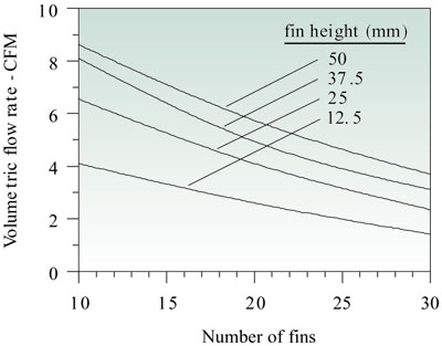
Figure 3. Effect of number of fins and fin height on volumetric air flow rate through heat sink.
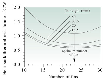
Figure 3 shows the flow, which the fan will deliver to each of the heat sink configurations, depending upon the number of fins and the height of the fins. Using the flow rate for each heat sink configuration and the methodology described in the earlier article [1] the corresponding heat sink thermal resistance was calculated for each heat sink to obtain the results shown in Figure 4. These results clearly show that for each configuration a minimum heat sink thermal resistance is achieved with 23 fins and that there is very little benefit in using a fin height greater than about 37 mm.
 |
Figure 4. Effect of number of fins and fin height of heat sink thermal resistance.
Of course, if a fan with a different fan curve is employed, the flow rates will change and the optimum heat sink design point may change as well. The important point is that to determine how a heat sink will perform in a given application both its heat transfer and pressure drop characteristics must be considered in concert with the pressure-flow characteristics of the fan that will be used.
It should also be noted that an underlying assumption for both this article and its predecessor is that all the flow delivered by the fan is forced to go through the channels formed between the heat sink fins. Unfortunately this is often not the case and much of the air flow delivered by the fan will take the flow path of least resistance bypassing the heat sink. Under such circumstances the amount of flow bypass must be estimated in order to determine the heat sink performance. An approach to estimate heat sink air flow bypass may be found in an article by Simons and Schmidt [3].
References
- Simons, R.E., “Estimating Parallel Plate-Fin Heat Sink Thermal Resistance,” ElectronicsCooling, Vol. 9, No. 1, pp. 8-9, 2003.
- Culham, J.R., and Muzychka, Y.S. “Optimization of Plate Fin Heat Sinks Using Entropy Generation Minimization,” IEEE Trans. Components and Packaging Technologies, Vol. 24, No. 2, pp. 159-165, 2001.
- Simons, R.E., and Schmidt, R.R., “A Simple Method to Estimate Heat Sink Air Flow Bypass,” ElectronicsCooling, Vol. 3, No. 2, pp. 36-37, 1997.


