Thermal transport from a heat sink creates a unique condition in heat transfer and fluid flow once it is placed on a PCB in an unducted fluid flow delivery system. Although a heat sink may appear structurally simple, the fluid flow through its fin field and thermal coupling between it and the surrounding create a rather complex problem. As a result, heat sinks are often selected by only considering the total device power dissipation as the criterion, rather than performing a detailed thermal analysis for its selection. In other words, it is the common syndrome of “I am looking for a heat sink to cool a 15W device!!!” Therefore, to assist in selecting the right heat sink for a given application and being able to examine different parameters impacting the heat sink’s thermal response, we present a detailed analytical model here.
A very common question is, “How much heat can we extract from a heat sink?” Before developing a model that can answer this question, we must clarify the ambiguity of the question. The answer is that you can extract as much heat as you want depending on the desired surface temperature. Also, since device surface temperature is equally ambiguous, the focus should be on the device junction temperature, Tj. Hence, by specifying the junction temperature, you can readily answer the aforementioned question.
Integral Model
Consider a commonly encountered package, a flip chip BGA with a heat sink residing on top side of the device, Figure 1.
 |
Figure 1. Heat transfer in a flip chip device with a heat sink.
Let’s employ the definition of the standard package resistors used in thermal management of electronics,
Rja = junction-to-ambient thermal resistance
Rjb = junction-to-board thermal resistance
Rjc = junction-to-case thermal resistance
Rcs = case-to-sink thermal resistance
Rsa = sink-to-ambient thermal resistance
Rsp = spreading thermal resistance
The heat sink thermal resistance (Rsa) is defined by the following equation,
 |
Where:
| Afin | = | heat sink fin area + Base area between fins |
| Cp | = | specific heat at constant pressure |
| h | = | heat transfer coefficient |
| = | mass flow rate, equal to |
|
| Vf | = | fluid velocity in the fin field |
| = | fin efficiency | |
| = | fluid density | |
| � | = | fin channel cross sectional area |
To determine Rsa, the heat transfer coefficient (h) and flow velocity within the fin field (Vf) must be determined. The heat transfer coefficient is obtained from equation 2 [1]:
Nu = 4.421 + 0.157 ( L* )-0.811 (2)
Where, Nu = 2hs/k and L* = L/2DHReD
DH = hydraulic diameter
k = fluid thermal conductivity
ReD =Reynolds number, equal to VfDH/�
s = fin-to-fin spacing
The next step of the calculation is to obtain Vf. Before moving ahead, we must note that calculating the fluid flow thru the fin field in an open channel (top and side bypasses) is a rather complex case since the flow is highly three-dimensional. The premature egress of the fluid from the fin field makes analytical prediction difficult. This is demonstrated in Figure 2, where the CFD simulation of the flow through the straight fin (conventional) heat sink clearly exhibits the three-dimensionality of the flow and shows how the flow departs from the fin field in an open channel system; this is typical of most applications.
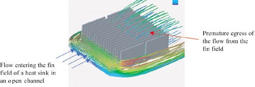 |
Figure 2. Computational fluid dynamics simulation of air flow through a straight fin heat sink. Premature flow egress from the fin field adversely impacts thermal performance.
The integral model estimation of the flow through the fin field is the subject of a future paper by the authors. Here, we have considered the flow bypass, V and the flow through the fin-field Vf, Figure 3.
 |
Figure 3. Regional flow designation
Applying conservation of energy to the heat sink, we have,
 |
Applying the continuity equation and assuming the Poiseuille flow in the channels created by the fins, we have,
VdAd = VfAf + V (Ad – Af) (4)
and
 |
Where:
| Ad | = | duct cross section |
| Af | = | channel cross section between fins |
| s | = | fin to fin spacing |
| L | = | fin length in the direction of flow |
| = | heat sink pressure drop | |
| V | = | bypass fluid velocity |
| Vd | = | duct (approach fluid) velocity |
| Vf | = | fluid velocity between fins |
For a given Vd, simultaneous solution of equations 3, 4 and 5 will yield Vf. Using the definition of Rja, let’s obtain an expression for Tj as the function of different parameters.
 |
Where, Ta is the approach fluid temperature to the device/heat-sink. The value of the spreading resistance (Rsp) is obtained from [2], Rsp stems from dissimilar contact areas between the source and the sink. That is when the heat sink is larger than the device, as shown in Figure 1. Or, if the heat sink is of the same size as the source, but heat is not spread uniformly.
Equation 6 along with equations 1-5, provide us with a versatile tool to answer the question of how much heat can be extracted from a heat sink, but, in addition, we will examine the impact of other parameters on Tj or Rsa. These parameters include, height, length and base area of the heat sink, heat sink material, Rjb and Rjc, number of fins and finally the total heat transfer from a heat sink.
Results
A parametric study was undertaken to evaluate the impact of these parameters on the thermal performance of the heat sink in an unducted flow. Table 1 shows values of different parameters used for Figures 4 to 12.
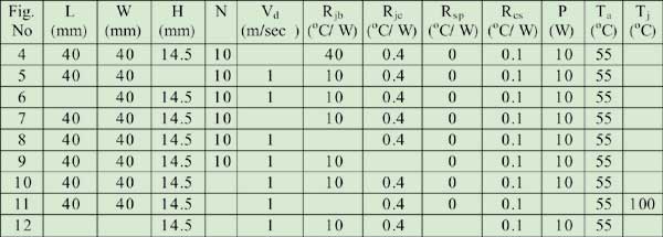 |
Table 1: Different values of parameters for test cases studied
Figure 4 shows the junction temperature as a function of velocity. This graph indicates that after a certain velocity, in this case about 3 m/sec, an increase in flow does not improve the performance by an appreciable amount. This is attributed to the leveling of the heat transfer coefficient and an increase of the pressure drop across the heat sink. Therefore, it shows that the model’s prediction corresponds to the expected physics.
 |
Figure 4. Junction temperature as a function of velocity.
Figure 5 shows the Tj as a function of fin height. Reducing fin efficiency after a certain height reduces the effectiveness of the thermal performance by increasing the fin height. In this case increasing fin height from 60 mm to 90 mm changes Tj by a mere 1.5oC.
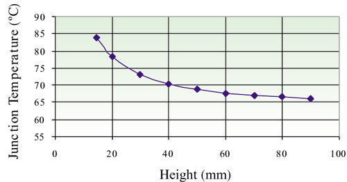 |
Figure 5. Junction temperature as a function of height.
Figure 6 shows the Tj as a function of fin length. Tj starts to increase after 150 mm. The increase in pressure drop and temperature of the air inside the fin-to-fin channels degrades the performance of the heat sink after a certain length. After this critical length, air temperature has essentially reached the heat sink temperature; hence no cooling can take place.
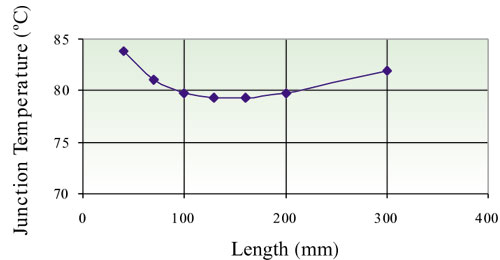 |
Figure 6. Junction temperature as a function of length
Figure 7 shows the Tj as a function of heat sink thermal conductivity and air velocity. This figure clearly shows that for the air velocity ranges considered, an increase of thermal conductivity from aluminum to copper has a minimal effect on the cooling process. For this case, spreading resistance was ignored.
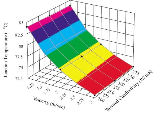 |
Figure 7. Junction temperature as a function of velocity and thermal conductivity.
Figure 8 shows Tj as a function of junction-to-board thermal resistance. A useful deduction from this graph demonstrates that at a certain value of Rjb, Tj can be reduced very rapidly by reducing the Rjb, but an increase of Rjb beyond this point does not have much effect on the junction temperature.
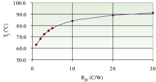 |
Figure 8. Junction temperature as a function of Rjb.
Figure 9 shows Tj as a function of junction-to-case thermal resistance. A reduction of Rjc has a significant effect on lowering Tj. The relationship is almost linear with no sign of reaching asymptotic condition.
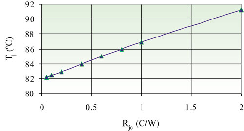 |
Figure 9. Junction temperature as a function of Rjc.
Figure 10 shows Tj as a function of number of fins. Increasing fin number beyond 15 causes Tj to increase. Even though the surface area is increasing, it causes a higher pressure drop in the heat sink, and therefore, a decrease in the flow rate. The exact number of fins varies with the air velocity.
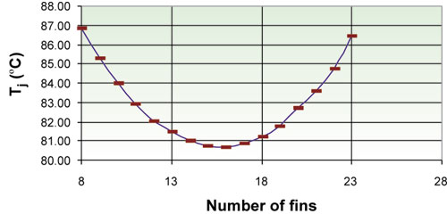 |
Figure 10. Junction temperature as a function of number of fins.
Figure 11 shows the maximum power dissipation as a function of the number of fins at different values of junction-to-board thermal resistance when Tj is 100oC. As in the previous case, there is an optimum number for fins when most heat transfer occurs. Graph also shows that the value of the Rjb does not have any effect on the optimum number of fins.
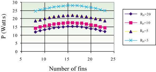 |
Figure 11. Maximum Power Dissipation as a function of number of fins
for different values of Rjb (Tj = 100oC)
Figure 12 shows Tj as a function of base area for a fixed size heat source of 15×15 mm. Fin spacing is kept constant for all dimensions. An important conclusion from this graph is that by increasing the size of the heat sink, spreading resistance increases such that, beyond the base size of 70 x 70 mm2, there is not much drop in Tj when compared to the same size heat sink with heat dissipation equally distributed at the base of the heat sink.
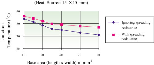 |
Figure 12. Junction temperature as a function of base area.
Conclusion
An integral model of a device with a heat sink has been developed that allows examination of the parameters impacting its junction temperature. The trend analysis was done for a prototypical heat sink that demonstrates the impact of parameters considered on junction temperature.
The model shows that in selecting and applying heat sinks it is not sufficient to consider only the heat sink thermal resistance as the sole criterion. Rather, it is necessary to look at the magnitude of junction temperature as the criterion for selection. All parameters, including the way the device is coupled to the board will impact thermal performance.
As one example, if thermal spreading is not considered while selecting a heat sink, the junction temperature can be under-predicted by 12%. Also, the model showed that the use of higher material thermal conductivity, e.g., copper, on most ASIC like devices provides minimal advantage.
In addition, the results showed that the total heat that can be extracted from a heat sink, for a set junction temperature and a given air velocity, is a function of number of fins and the device thermal characteristics, Rjb and Rjc. Irrespective, for a given Rjb, there is an optimum point with respect to heat transfer from the heat sink and the number of fins.
However, the model and approach shown here provide a versatile tool to design and specify a heat sink that is best suited for a given application. As it is clear from the model, obtaining approach air velocity and temperature is instrumental in the successful design and selection of the heat sink.
References
- Tavassoli, B., “Heat Transfer Coefficient Correlation for High Performance Heat Sinks”, Internal memorandum, ATS-08876-99-01, Advanced Thermal Solutions, Inc., 1999.
- Yovanovich, M.M., Muzychka, Y.S., and Culham, J.R., “Spreading Resistance in Isoflux Rectangles and Strips on Compound Flux Channels”, AIAA Journal of Thermophysics and Heat Transfer, Vol. 13, No. 4, Oct-Dec., 1999, pp. 495-500.


