Data centers are mostly managed by overly conservative thermal management approaches [1]. The typical thermal solution for data centers is perimeter computer room air handlers (CRAH). The traditional cooling method includes supplying air through raised floor plenum that is blown by the CRAH blowers, and the chassis fans, typically located at the rear end of the IT equipment, pull the air across the server collecting the heat, and the exhaust air from fans is again collected by the CRAH return. This architecture provides adequate cooling for rack densities below 5 kW. However, as the rack densities raise beyond 5 kW, the removal using CRAH based cooling becomes challenging [2].
In order to address this issue, data centers have adopted the concept of close-coupled cooling, i.e. bringing the cooling source closer to the IT equipment. Some of the close-coupled cooling solutions are overhead cooling, rear-door heat exchanger cooling, in-row cooling, bottom located cooling, etc. The key objectives of close-coupled cooling is to enable a controlled cooling of the IT equipment, flexible as well as modular design architecture, and containment of hot air exhaust from the cold air [3].
The thermal performance of the proposed new solution is being evaluated and analyzed for its energy efficiency using commercial CFD software [4]. A computational model of a small size data center room is developed. Larger axial fans are selected and placed at rack-level which constitute the rack-fan wall design. The model consists of 10 electronic racks each dissipating a heat load of 8 kW. There are two rows with five racks placed on each row, as shown in Figure 1. The room is modeled to be hot aisle containment, i.e. the hot air exhaust exiting for each row is contained and directed within a specific volume. Each rack has passive IT servers with no server fans and the servers are cooled by a rack fan wall. The cold aisle is separated from the hot aisle by means of banks of heat exchangers placed on the either sides of the aisle containment. There is no raised floor plenum. The air flow movement (for Case 1) includes the cool air (~25°C) being pulled in by the rack fans across the servers. Then the exhaust air (~37°C) takes a turn passing through the heat exchanger units placed on either side of the hot aisle containment. The heat exchanger units are located such that it would eliminate the risk of having cooling coils at the top of the electronic racks. Three 1U servers are cooled by 3 120 mm parallel axial fans.
Based on the placement of rack fans, the design is divided to three sub designs:
Case 1: Passive heat exchangers (HX) with rack fan walls-Φ120mm;
Case 2: Active heat exchangers (HXs coupled with system of axial fans-Φ200mm) with rack fan walls;
Case 3: Active heat exchangers (HXs coupled with system of axial fans-Φ200mm) with no rack fans.
The fan energy was calculated based on the pressure and flow parameters obtained for all three configurations. The input parameters for the heat exchanger coils remained the same in all cases. The computational data obtained is used to compare and contrast for the best case close-coupled cooling configuration.
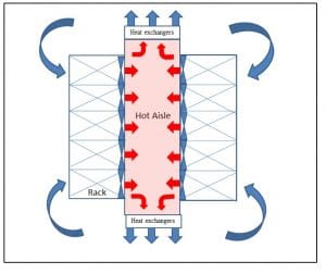
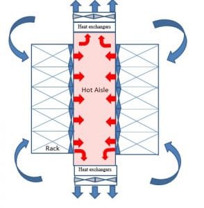
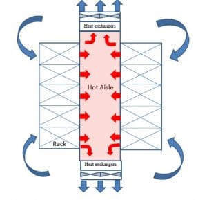
Figure 1: Schematic of End-of-Aisle Close-coupled Cooling design
From the initial set of studies the cooling system showed acceptable temperature () and air flow profile based on the given boundary conditions. The volume resistances considered for the Case 1 design are for low resistance IT systems. However, it has been seen that such a system in the presence of air movers arranged in series with the IT rack fans or in series with heat exchangers can handle higher system resistance. The top section of servers showed higher exhaust temperatures but overheating of the IT is not observed.
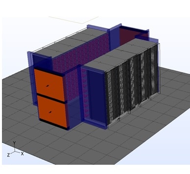
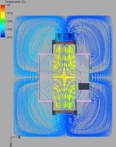
Case 2 has been an over pressurized system compared to other two cases. This can be addressed by increasing the hot aisle volume. It has also been noticed that the distance between heat exchangers and the axial fans in series for Case 2 and Case 3 is of importance. If the fan systems are closer to heat exchangers, then they would pull the air fasteners across heat exchangers coils reducing the thermal performance of the heat exchanger. Further analysis is needed to determine the best case cooling design. The analysis will include cooling redundancy during failure conditions, system air flow behavior when it is not isolated i.e. if neighboring IT rows are present and exploring the usage of blowers instead of axial fans as air movers.
Overall, the current study proposes a new cooling design that addresses the challenges for placing cooling coils at the top of the IT or at the bottom of the IT. The CFD analysis comparing the thermal performance of all three cases gave multiple design considerations to be made to select a certain design case. Based on the results obtained, Case 3 showed lower fan energy as well as capability to handle denser IT systems.
References
[1] Y. Joshi and P. Kumar, Energy Efficient Thermal Management of Data Centers, New York: Springer, 2012
[2] J. Bean and K. Dunlap, “Energy-Efficient Data centers,” ASHRAE Journal, 2008
[3] Mission Critical, “Close-coupled cooling system is right fit for data center,” May 2016. [Online] Available: http://www.missioncriticalmagazine.com/articles/88414-a-close-coupled-cooling-system-is-right-fit-for-data-center
[4] Future Facilites, “Our Solutions,” 2016. [Online]. Available: http://www.futurefacilities.com/solutions/data-centers/


