Electric vehicles are poised for a rapid growth phase with the combined effect of longer range, lower battery cost and faster charging rate. In particular, sales of plug-in electric vehicles (PEV) have tripled since 2013 and continue to grow at over 40% a year. It is expected that at these growth rates, 8 out of 10 new cars sold globally in 2030 will be a PEV. In some countries like Norway, nearly a third of new cars sold currently are electric.
With the rapid adoption of PEVs comes some unique thermal challenges. The PEV has different types of heat loads than internal combustion vehicles, particularly in the batteries and on-board electronics for power conversion and management that include the on-board charger, DC to DC converter and inverter. While battery thermal management deals with bulk heat removal, the power electronics requires heat removal from tightly-packed, concentrated heat loads. Since battery thermal management is an important topic by itself and has already been addressed in several publications [1], the main focus of this article is on thermal management of the power electronics components.
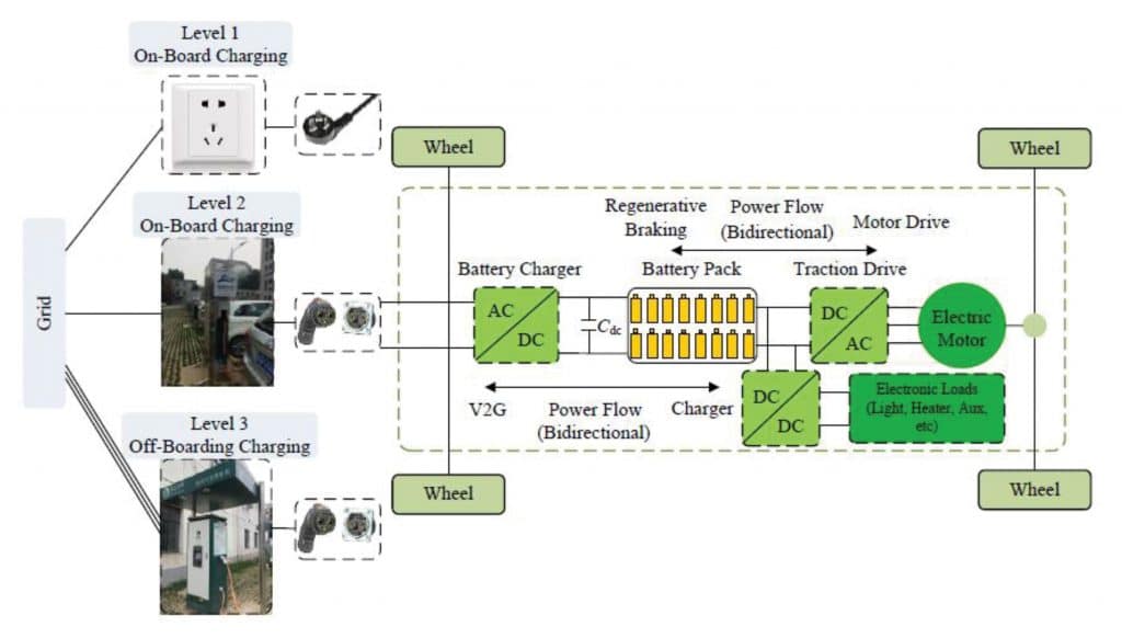
One of the key challenges in PEVs is the time required for charging the batteries and the availability of power outlets. Charging of PEVs is classified into Levels 1, 2 and 3 by the Society of Automotive Engineers.
- Level 1 – Slow charging at 120/240V AC and 15 amps using the standard available household power outlets up to 3.3kW. The AC to DC power conversion is done on board.
- Level 2 – Medium rate charging using 240V AC and 60 amps up to 14.4 kilowatts from power outlets specifically made for PEV charging. The AC to DC power conversion is done on board.
- Level 3 – Fast charging used specially for PEV charging rated over 14.4 kilowatts. In this case, the AC to DC power conversion is usually done off-board.
On-board chargers, used primarily for AC to DC power conversion, contain several types of power electronic devices like MOSFETs, diodes and magnetics. The advantage of having an on-board charger (compared to off-board) is that the vehicle can be charged from AC power outlets. However, it also requires the vehicle to carry the extra weight of the power electronics and heat sinks. Newer designs have integrated multiple functionalities into the charger to include bi-directional power conversion [4] as well as DC to DC conversion. This makes the overall design more compact. Figure 1 illustrates the multiple functionalities that can be included in the on board charger along with the different levels of charging [3].
The charger electronics need to be packaged inside an enclosure which has to be sealed to prevent environmental contamination. This requires that the heat loads be thermally connected to the enclosure walls in order to efficiently dissipate the heat. The enclosure wall, therefore, need to function as a heat sink in order to dissipate the heat to the outside air (or liquid). To ensure that the heat loads are thermally connected to the enclosure wall, a suitable thermal interface material which provides not only good thermal conduction but also the required electrical insulation between the device and the enclosure must be selected. The outside ambient air temperature can be as high as 50C (worst case scenario lik).
At Level 1 charging, the required R-sa (sink-to-ambient thermal resistance) for the heat sink should be less than 0.24 oC/W for a 3.3kW charger based on the above thermal parameters. Figure 2 shows the thermal resistance network for multiple power devices mounted to a common heat sink which was used to calculate the required R-sa.
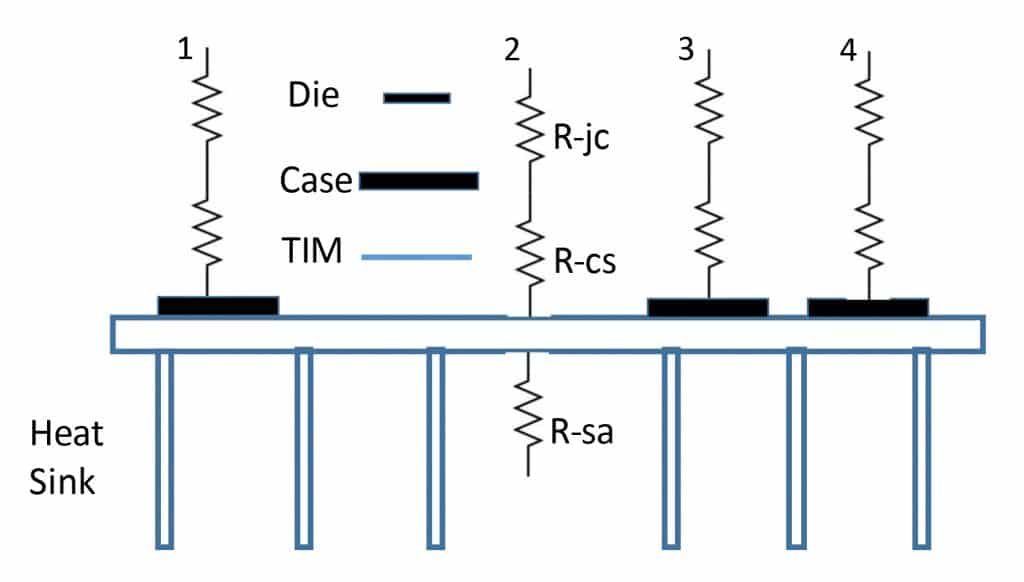
For this relatively low power case, the heat load can be easily removed by forced air convection from the outside of the enclosure walls using a fan. Considering that the charging load occurs when the vehicle is stationary, there is no additional airflow benefit due to vehicle movement. Since there is no need to use the vehicle liquid cooling systems at Level 1, the systems integrator has greater flexibility on how to position the charger inside the vehicle. The weight of the charger can be significantly reduced by adding heat pipes to the heat sink base to spread the heat from the concentrated heat loads. The weight (& space) savings can be a double bonus in terms of increased vehicle range and lesser space requirement. Heat pipes can also be used to extend the feasibility of air cooling to higher power densities. Figure 3 shows an example of a heat pipe heat sink assembly for power electronics applications.
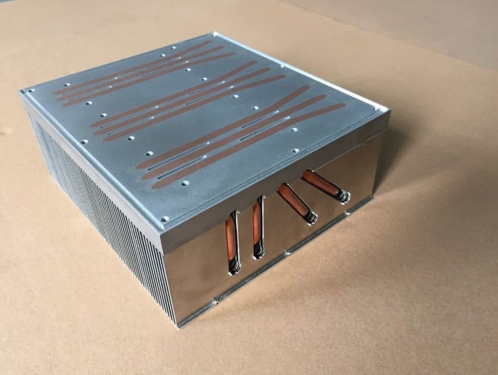
It includes multiple heat pipes embedded into the aluminum base for better heat spreading from concentrated heat loads. Heat pipes are also used to transport heat into the aluminum fins for better fin efficiency.
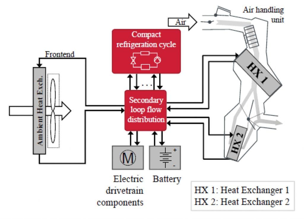
The system consists of a central refrigeration system that is cooled by a radiator and provides chilled liquid to multiple sub systems – like HVAC, batteries, chargers and other electronic components. These sub systems have their own heat exchangers, pumps and controllers to provide the required cooling capacity for their respective heat loads. At the component level, a suitable liquid cold plate (LCP) is required to cool the heat loads in the charger. Figure 5 shows some of the commonly available LCP design options that can be used to extract the component heat loads.

While the tube and channel types can be used for lower power densities, the extended fin type is more suitable for higher power densities. The final selection of the LCP type depends on a variety of factors and the LCP design typically must be customized to address the layout of heat loads, power density, pressure drop constraints and material compatibility with the rest of the cooling system. It also need to be mechanically integrated into the charger enclosure (see Figure 6) to ensure that the electronic components are sealed.
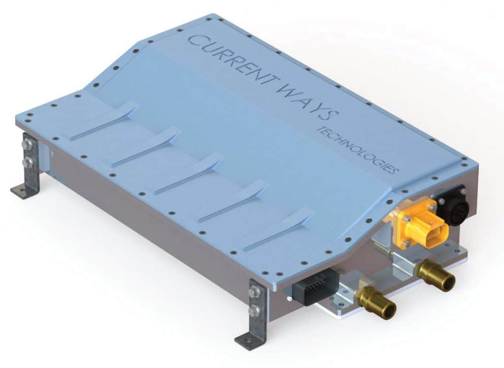
If current trends continue, it is expected that the requirement of fast charging (Level 3) will continue to accelerate. At very high power levels, it is likely that the AC-DC power conversion will be carried out off-board to avoid the additional space and weight required in the vehicle. For example, the Tesla Supercharger can provide 120 kW of DC power from the charging station and charge the Model S up to 50% in 30 minutes. However, until these Supercharging DC stations become as ubiquitous as gas stations, it is likely that PEVs will continue to carry an on-board charger to provide the flexibility for charging from more commonly available AC power outlets [2]. The future thermal management of on board chargers will likely evolve to use high-end LCPs integrated into the charger enclosure along with intelligent interfaces with the vehicle liquid cooling system. Also, the thermal engineer will have to engage very early in the vehicle design cycle to be able to dissipate all the heat loads efficiently including charger, inverter and batteries.
ACKNOWLEDGEMENTS
The author would like to thank his colleagues, Andy Grunes, Brad Whitney and Sachin Kanetkar, for providing valuable inputs and illustrations for this article.
REFERENCES
[1] “A comprehensive thermal management system model for hybrid electric vehicles”, Sungjin Park, Doctoral thesis, Department of Mechanical engineering, University of Michigan, 2011.
[2] “Fast charging electric vehicles using AC”, Masters Thesis, Joachim Johansen, Department of Electrical Engineering, Technical University of Denmark, 2013.
[3] “An integrated multi-functional bidirectional AC/DC and DC/DC converter for electric vehicle applications”, Liwen Pan, Chenging Zhang, Energies 2016, 9, 493.
[4] “Design of a bidirectional on-board battery charger in Hybrid electric vehicle applications”, Masters Thesis, Mehdi Erfani, Department of Energy and Environment, Chalmers University of Technology, Sweden, 2011.
[5] “Heat flow rate based thermal management for EV using a secondary loop heating and cooling system”, T. A. Weustenfeld et al, Audi AG, http://iftbs.de/images/Dokumente/vtms_ weustenfeld_energy_flow_tme.pdf

