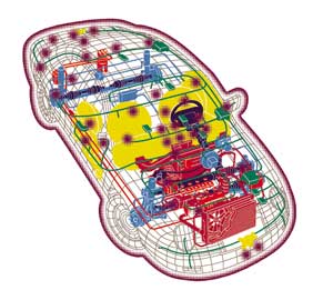
Electronic content in cars and trucks has significantly increased in the last 30 years. Much of the functional content of these vehicles is now generated or controlled by electronic systems. This trend will continue in the future, as more mechanical functions are converted to electronic and electrical functions. A list of many current automotive electronic functions can be found in Table 1.
Table 1. Current Automotive Electronic Functions
 |
Where Are We Today? | |
|
|
|
|
|
|
||
The annual growth in the worldwide automotive OEM electronics market is expected to be about 6% in the next 4-5 years [1]. Market growth could be as high as 50% annually for automotive wireless hardware and services.
Although any discussion of automotive products brings to mind the family sedan, the automotive market and the electronics required for this market is very diverse. Electronic controls are used extensively in heavy-duty vehicles such as cement trucks and agricultural vehicles as well motorcycles and lawn mowers. Added to this diversity in size is a wide range of gas and diesel internal combustion engines. Some recently introduced vehicles – hybrid cars – use internal combustion engines in conjunction with electric drive motors. Electric vehicles use electric motors alone without internal combustion engines. It is anticipated that fuel cell based electric vehicles will go into production some time late in this decade. These vehicles will use high power motor controls and drive electronics that will likely dissipate kilowatts of thermal energy.
These new applications will result in a proliferation of cooling issues for the automotive electronics industry. This article examines some of the cooling challenges of these future automotive electronic systems.
Cost, Size, and Reliability
The requirements of low cost and small size is a given for nearly all commercial electronics applications. This is also true for automotive electronic systems and, as is the case with many consumer electronic products, price is a major driver of the hardware design. One example can be seen in the history of typical engine control modules (ECMs) shown in Figure 1. Over time, the size and cost of the typical ECM has decreased while the required functionality and operating temperatures have significantly increased.
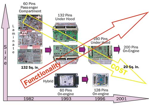 |
Figure 1. History of typical engine control modules (ECMs).
Although both consumer and automotive electronic hardware trends push suppliers toward smaller size and lower cost, there are significantly higher requirements for operating life, reliability and operating environment in automotive applications. Automotive safety issues as well as customer expectations require flawless function under all weather and operating conditions for 10 years or more. Hence, the challenge for automotive electronic hardware designs and the resident cooling technology is not only achieving small size and low cost, but also high reliability in high ambient temperatures. Figure 2 shows a summary of typical automotive operating environments [2]. In the future, ambient temperatures and thermal cycle life requirements are expected to increase.
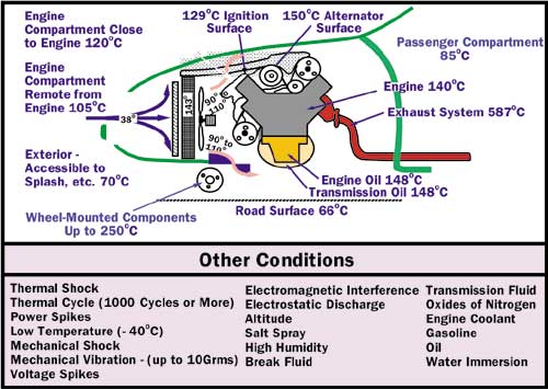 |
Figure 2. Summary of typical automotive operating environments.
Some Typical Applications
The need for both low cost and high reliability has driven most automotive electronic hardware cooling designs toward simple and inherently reliable technologies. Most designs use conduction to transport heat from electronic components to the surface of the electronic enclosure and natural and/or existing convection to dissipate this heat into the ambient air.
For instance, consider the automotive engine control module (ECM), which is an excellent example of current automotive thermal design practices. Many ECMs are mounted in the engine compartment and can experience ambient operating air temperatures as high as 105°C to 125°C. Typical power dissipation for these modules can range from 10-30 watts. Most of the integrated circuits used in these modules are designed to operate with a maximum junction temperature of 150°C.
These requirements translate into junction to case thermal resistances as low as 2.5°C/W and case to ambient thermal resistance values of 1-3°C/W. Airflow can vary substantially as a function of mounting location inside the engine compartment and vehicle operating conditions.
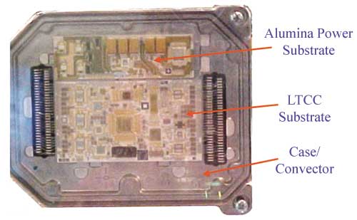 |
Figure 3. Ceramic-based ECM.
Figures 3 and 4 show some typical examples of under hood mounted ECM thermal designs. Figure 3 shows a ceramic-based ECM. In this example, the low temperature cofired ceramic (LTCC) control board and the thick film alumina power substrate are bonded directly to a case/convector with a thermally filled adhesive. Since alumina has significantly better thermal conductivity than LTCC, it is used on the power substrate for lower junction to case thermal resistance.
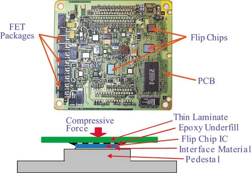 |
Figure 4. ECM circuit board, where both flip chips and packaged power transistors (FETs) are mounted directly to a laminate PCB.
Figure 4 shows an ECM circuit board where both flip chips and packaged power transistors (FETs) are mounted directly to a laminate PCB. The power dissipated by the FET packages is transferred through the PCB into the case, which contacts the area of the PCB directly underneath the FET devices. The power dissipated by the flip chips is also conducted to the case. This transfer is facilitated by direct contact between the case and backside of each flip chip. This structure is shown in cross section in the lower part of Figure 4. The interface material is typically a thermal grease.
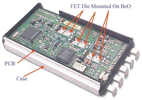
In higher power applications, such as power steering controllers, where junction to case thermal resistance values must be 1°C/W or less, bare die are soldered to high thermally conducive substrates. One example of this approach can be seen in Figure 5, which shows an immersion cooled controller for an electro-hydraulic steering motor. In this case, the power FETs used to drive the motor are mounted to BeO substrates, which have been soldered to the case. In addition to BeO, other types of materials used for these high power output structures include AlN, Cu (where dielectric isolation is not required), and metal core substrates.
Figure 5. Immersion cooled controller for an electro-hydraulic steering motor.
The Car of the Future
There are a number of clear trends in vehicle design that will cause significantly greater power dissipation for some electronic applications. As a result, cooling technologies that have not yet been applied to automotive electronics or have only seen limited use will be required for some applications.
The ongoing trend of combining electronic control with simplified mechanical systems into so-called mechatronic systems [3] will continue with steering and braking systems migrating toward more electronic functionality. In most modern vehicles, the steering system consists of mechanical and hydraulic linkages between the steering wheel and tires. Anti-skid braking systems use an electronic controller to release brake pressure during skid but the force applied to the brake pads is accomplished with hydraulic systems.
There are a number of advantages to brake-by-wire and steering-by-wire systems over current systems. These include improved fuel efficiency, simplified vehicle assembly, and enhanced functionality. Since these systems require very high reliability, it is anticipated that replacement of mechanical parts with electronic controls will be incremental over time and may use redundant electronic or mechanical parts until a high level of reliability is demonstrated. Motors will be used both to actuate the brakes and to turn the wheel. The motor control electronic modules will dissipate 40-60 watts of power. This power level will be coupled with ambient operating temperatures of 105-125°C. As a result, cooling technologies will be required with less than 1°C/W for both junction to case and case to ambient thermal resistances.
As the electronic content of vehicles increase, the need for more power from the electrical generator (alternator) increases. Increased current requirements for high power applications reduce the electrical power available at the load due to increased voltage drops in the wiring harness. As a result, some traditional 12/14-volt automotive electrical systems will migrate to 36/42-volt systems, which have the capability to deliver higher power levels at lower current. This change will require the use of a new generation of electrical generators.
Some of these high power generators will be mounted in the main automotive drive train probably between the engine and transmission. In this location, the generator can be designed to also act as the starter motor. Electronic controllers for these machines may dissipate a kilowatt or more of waste heat in ambient air temperatures of 95-115°C. Since this is an order of magnitude more heat dissipation than current automotive electronic modules, the cooling technology used will be critical to the performance and cost of these systems.
Although internal combustion engines dominate the current automotive market, alternative power train systems have been introduced into the market place. The most popular of these systems use hybrid power trains composed of both electric motors and small efficient internal combustion engines. Significant resources are also being expended to develop fuel cells as environmentally clean mobile energy sources by automotive manufactures. Although battery based electric vehicles have been manufactured in limited volumes for several years, most of these vehicles are limited in both range and performance. The development of practical, low cost fuel cells will effectively eliminate these limitations giving full electric vehicles equivalent range and performance to conventional internal combustion vehicles.
The added advantage that hybrid and particularly fuel based electric vehicles have in reducing CO2 emissions could eventually cause these power trains to dominate the automotive market. Electric drive motors require complex current switching and control electronics with many of the same issues discussed above for 42V starter/generator controllers. The major differences will be even higher levels of voltage, current, and heat energy dissipated by electronic control systems.
Various wireless communication and entertainment applications will become more popular in vehicles. Although there will be some applications with thermal dissipation issues, the relatively low power dissipation and low operating ambient (85°C) of these in passenger compartment systems will not cause significant thermal management issues. The same can be said for most new safety related systems that will see high penetration into new vehicles. These applications include occupant sensing, obstacle detection, and collision avoidance.
Summary of Thermal Requirements
A summary of future trends for automotive electronics thermal requirements can be seen in Figures 6 and 7. Figure 6 shows the anticipated dissipated thermal power that will be required for discrete transistors (FETs and IGBTs) as well as for smart power drivers. Discrete transistor dissipation levels will be paced by hybrid and electric drive vehicles. Increasingly complex and up-integrated internal combustion engine controllers will drive smart power device dissipation levels. In many applications, transient conditions can generate power dissipation values several times higher than the steady state values. These transients can last for several seconds.
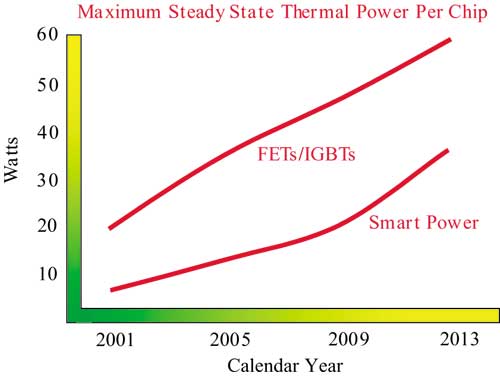 |
Figure 6. Anticipated dissipated thermal power that will be required for discrete transistors (FETs and IGBTs) as well as for smart power drivers.
Figure 7 shows a thermal power dissipation summary for many current and future automotive electronic systems. The applications that operate in the highest ambient temperature (i.e., ignition) and that have the highest power dissipation (i.e., hybrid and electric vehicle motor controllers) present the greatest challenge to electronic cooling system design. As can be seen from this graph, hybrid/EV and starter/generator controllers will need to dissipate 10-100 times more thermal power than more typical automotive electronic systems. These applications will require the use of more efficient and complex cooling technologies than those used in most automotive electronic applications today.
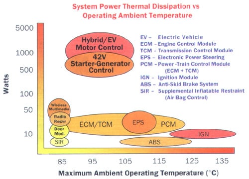 |
Figure 7. Thermal power dissipation summary for many current and future automotive electronic systems.
Cooling Technology Issues
Cooling solutions used for other types of electronic applications do not always translate well into the automotive environment. This is particularly true if the automotive application is mounted under the hood or in other locations outside the passenger compartment. These applications typically utilize sealed product cases and are subject to the extreme automotive environment. When these issues are considered with the need for higher power cooling technologies, several cooling technologies seem to have potential for use in automotive applications. These include pumped liquid cooling, heat pipes, thermo-siphons, and advanced thermal materials. Thermal transients may require the use of solid-to-solid, solid-to-liquid, or liquid-to-gas phase change materials.
Any material used in these cooling systems must be chemically and mechanically stable over the life of the vehicle. Materials must be low cost and compatible with electronic devices and materials. In addition, any accidental release of these materials must not generate any significant safety hazards to humans or the environment. Any system that uses a liquid or gas other than air must be able to contain these materials under all use conditions for life of the vehicle.
Some types of cooling solutions may inherently add complexity to both electronic product and vehicle assembly. Examples of this issue are the pumps and plumbing required for many liquid-cooling systems. Cooling systems that can minimize electronic and vehicle assembly steps will have a major advantage over more complex systems.
Summary
There will be substantial expansion in the number and application rates of many electronic functions in the automotive market. The next ten years will also see a proliferation in the types of vehicle power trains offered to the consumer. This trend will create many new applications for automotive electronics. Many of these electronic applications will require high performance electronic cooling technologies that are not typically used in the automotive environment. The challenge will be how to apply these technologies in high volume with low cost and high reliability.
References
- “The Worldwide Market for OEM Automotive Electronics – 2001 Edition”, published by The Freedonia Group.
- Information on automotive environments and electrical component test standards can be found at the Automotive Electronics Council web site: www.aecouncil.com.
- Myers, Bruce A., Burns, Jeff H. and Ratell, Joseph M., “Embedded Electronics in Electro-Mechanical Systems for Automotive Applications”, SAE 2001 World Congress, SAE Technical Paper Series, No. 2001-01-0691.

