BACKGROUND
In a proposal submitted to the Air Force in November of 1968, Collins Radio Company described ways to improve the electronic industry’s understanding of thermal management and predictive techniques [1]. This article briefly describes that proposal and discusses what aspects of electronics cooling have changed over the past five decades and what things have not.
November 1968 was an interesting period in the histories of the aerospace and the electronics industries. The Space Race was on, and there was considerable funding available to support advances in both technologies. Apollo 7, which was the first manned flight after the tragic Apollo 1 fire of 1967, had occurred just a month earlier. Apollo 11 would successfully land on the moon in only nine months.
The Collins Radio company newsletters for November and December of 1968 discussed how the company’s communication equipment had been used on the Apollo 7 flight and the Apollo 8 flight scheduled to orbit the moon in December, in addition to other events such as the upcoming first flight of the Boeing 747 in December [2]. Test activities in the heat transfer lab during the fall of 1968 included measuring the pressure drop and thermal performance of air cooled heat exchangers for high power radios, characterizing a vendor’s fan, testing the performance of a liquid cooled heat exchanger, and demonstrating the fire resistance of a cockpit voice recorder. Other than the last test, which appears to have involved the use of a blow torch, all of these activities are still commonly done in the current Rockwell Collins Heat Transfer lab.
OVERVIEW OF THE PROPOSED RESEARCH
The proposed research for the Air Force included four primary tasks. The first task was to gather and collate data from the published literature to better understand which areas needed further work. The second step was to conduct fundamental research to fill in those areas that were found to be lacking in a complete knowledge. The third would be to integrate the combined literature and test data into sub-routines to extend the capabilities of existing computer-based modeling. Finally, test structures would be built and tested to validate the new computer analysis capabilities.
The proposal’s authors felt that there were two primary factors that inhibited accurate electronics cooling predictions. The first of these was the need to experimentally assess the heat transfer characteristics of different fluids and develop methods to compare the effects of the combined properties of different fluids when used in boiling heat transfer.
The researchers felt that two-phase cooling using new liquids, would be essential to meet severe thermal challenges and that the use of these new liquid coolants would require new methods to assess their performance in a given application so that the optimal fluid could be selected for a specific design.
The second gap identified in the proposal was the limited knowledge of component level thermal resistance values. While the researchers were confident in their ability to predict system level temperatures, they lacked accurate methods to determine component-level temperature rise. In effect, they were proposing methods to better define component thermal resistance values, such as the terms θj-c and θj-a , that we use today. Accurate prediction of component thermal resistance continues to be a challenge, although the types of packages for which these values applied have changed. In the 1968 proposal, the package style for which thermal resistances that were to be to experimentally determined were flatpacks, TO transistors and carbon resistors.
A primary goal of the research was to gather data to improve a modified version of the “Thermal Network Analyzer Computer Program” that was developed by Lockheed in the 1950’s. That program may have been the same as one that was described by NASA, which reported that it could solve steady and transient thermal problems defined by up to 400 nodal points and 700 resistors [4]. The original program, which had been developed for airframe analysis, was modified to include subroutines that accounted for heating of the coolant, radiation effects, phase transition at nodes, and aerodynamic heating. The proposal stated that this thermal analysis tool had predicted component temperatures within 10% on equipment used in the Mercury, Gemini and Apollo systems.
The proposed work would seek to enhance the program’s analysis capabilities through experimental testing that better defined the thermal resistances at each end of the thermal path, i.e. the convective thermal resistance as a function of local boundary layer effects for different fluids and component level thermal resistances. Ultimately, the proposal envisioned a general analysis approach that would be accessible to the entire avionics industry. This analysis capability would allow designers to accurately determine component temperatures so that the thermal management system cost and weight could be minimized such that temperatures would be just low enough to meet reliability requirements.
CHANGES SINCE 1968
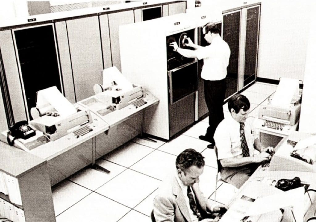
It is illuminating to compare the information provided in the proposal, as well as other contemporary material, to today’s state of the art. The most significant change over the past ~50 years has to be in computational capabilities. The proposal indicated that the available computer facilities consisted of two Collins C-8500 computers (Figure 1) that had a “memory size of 65,536 words, each word having 32 bits or 4 bytes”, i.e. memory of 256kB. Input took place through punch cards and tape drives. Another computer, a Univac U-1108, was available through a data link and had a memory size of 65,536 words, each with 36 bits.
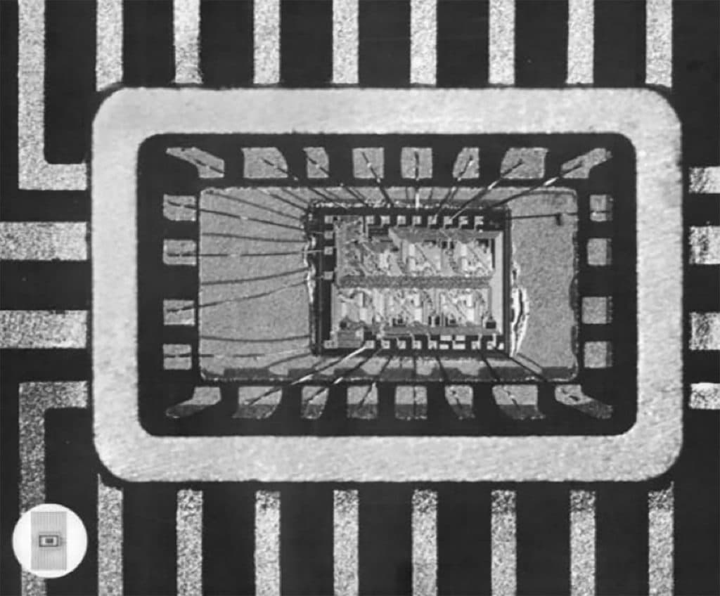
A primary reason for the significant advances in computing capabilities relative to 1968 is the evolution of integrated circuits and their packaging. Figure 2 shows a 24 lead hermetically sealed package with a wire bonded silicon die that was featured as the cover picture on the November 1968 issue of the company magazine, Pulse [2].
In contrast, Figure 3 shows a system in package currently used in avionics products. This package includes two flip chip Application Specific Integrated Circuits (ASICs) under a silicon interposer onto which memory die are wirebonded. The entire package is packaged as a Ball Grid Array (BGA).
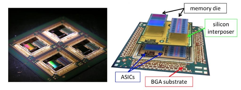
Figure 4 shows a transponder unit from the late 1960’s. The electronic packages used thru-hole technologies, were primarily analog, and likely had relatively uniform power dissipation across all the circuit cards in the assembly.
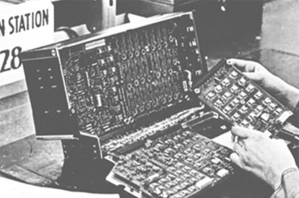
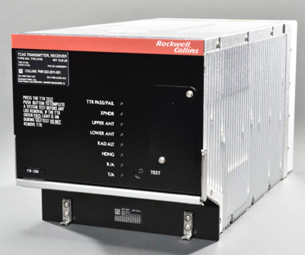
Figure 5 shows a system currently used on the Boeing 787 that includes weather radar, terrain collision avoidance, terrain awareness, and transponder functions. The system has much larger digital content and the circuit card assemblies use surface mount components.
Power dissipation in these types of systems tends to be less uniform than in its predecessors; instead much of the power dissipation tends to be isolated to a few components. Because the systems shown in Figure 4 and 5 were both designed to conform to standard interfaces between aircraft and avionics, they have the same general size and shape. Advances in microelectronics did not lead to smaller individual avionics chassis, but instead allowed multiple functions to be integrated into a single module.
While many things have changed since 1968, others have not. Figure 6 shows a picture of the Collins Radio centrifuge described in the 1968 proposal and the same centrifuge that is still used by Rockwell Collins. Of the five specific pieces of test equipment shown pictorially in the proposal, three are still being used today. The primary change apparent for these three test units (the centrifuge, an explosion chamber, and an environmental chamber) after nearly 50 years is that computers are now part of the test equipment.

DISCUSSION
Reviewing historical technical documents such as this proposal provide insight into what aspects of technology have changed over time or, in the case of test equipment like the centrifuge, have not. One clear change has been the level of dependence of design on computer resources. It is unlikely that any modern tool could operate on a system with only 256kB of memory, let alone do detailed analysis that predicts temperatures within 10% of test values. The fundamental analysis approaches in the analysis software have probably not changed all that significantly since 1968.
The primary changes are increased resolution with more detailed models, the algorithms that allow for efficient solution of these much higher resolution analyses, significantly faster processing, and the more flexible user interfaces. The proposal described that computer-based thermal analysis was conducted by experts who were well trained in how to use the software.
Many of today’s most popular thermal analysis tools are designed for more casual user who may have limited understanding of the detailed nuances of the code’s functions. Expert analysts are more likely to be needed to address complex optimization challenges that involve multi-disciplinary solutions that address topics as diverse as thermal, materials, structural, reliability, electrical, and optical engineering. Future improvements to software will likely continue to exploit the increasing processing capabilities to bring these multi-disciplinary analyses into the hands of the more casual user. Perhaps they will someday achieve the goal of the proposal and fully optimize thermal designs to meet reliability requirements, and no more than that, while minimizing cost and weight.
Looking back at information from that era, it is also clear that electronics miniaturization has made great strides over the past ~50 years. This has been accomplished in large part through advances in semiconductor technologies, but improved packaging has also played a significant role. The combination of new semiconductor technologies, such as Indium Phosphide and Gallium Nitride, and greater use of 3-D packaging will undoubtedly lead to continued device-level miniaturization. However, functional miniaturization does not inherently lead to system miniaturization. As shown in the transponders shown in Figure 4 and Figure 5, smaller components do not necessarily lead to smaller systems.
As has occurred in mobile electronics over the past decade, miniaturization instead increases the amount of functionality that is packed into the same space. This is particularly true in cases like commercial avionics, which must be designed to interface standards so that common equipment can work in future as well as legacy platforms. Changing standard interfaces between sub-systems can be quite difficult once those standard interfaces have been adopted; consider, for example, how many light bulbs continue to use light bulbs with the Edison screw socket more than 100 years after it was first licensed.
REFERENCES
- Development of Advanced Cooling Techniques and Thermal Design Procedures for Airborne Electronic Equipment, proposal submitted to United States Air Force Command, November 1968
- http://rockwellcollinsmuseum.org/collins_pulse/issues.php
- https://www.rockwellcollins.com/Products_and_Services/ Commercial_Aviation/Flight_Deck/Surveillance/ Transponders/TPR-901.aspx
- H. D. Sakakura, “Thermal Network Analyzer Program”, AECNASA Tech Brief 69-10239, July 1969, https://ntrs.nasa.gov/ archive/nasa/casi.ntrs.nasa.gov/19690000239.pdf


