Reticulated Metal Foams (RMF) are cost-effective and ultra-high-performance thermal management materials that can be integrated with electronic devices and modules. RMFs are compatible with DI water, inert fluoro-carbons, jet fuel, and inert gases.
STRUCTURE OF RMF
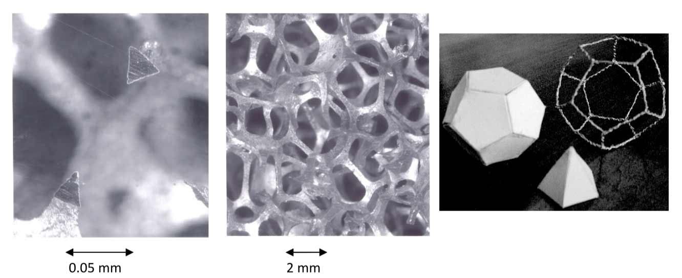
There are quite a few ways to fabricate RMF [1], however the investment casting method of manufacturing produces the most desirable material properties. In the as-fabricated state, the isotropic RMF consists of randomly oriented polygon shaped cells that can be approximated as dodecahedron, Figure 1 [2,3,4]. Notice that the cross sections of roughly 2 mm long solid ligaments are mostly triangular. The geometry of RMF cell structure and the high purity and ductility of its metal produce the most desirable characteristics for heat exchanger (HX) applications. The physical dimensions of its structure, as shown below, does not allow boundary layers to grow and introduce enhanced mixing through eddies and turbulence. These features result in a high local film coefficient. RMFs metal foams commonly have 5, 10, 20 and 40 pores per inch (PPI) configuration and 4-13% theoretical density fabricated with, 6061 Al, C10100 Cu or Ag, among others. The important parameters of the RMFs are; thermal conductivity, heat transfer surface area, high mechanical ductility and compliance.
Thermal Conductivity:
The foam manufacturing process preserves the high purity of the material in the RMF. The thermal conductivity of 6061 Al and C10100 Cu, most common RMF materials, are about 170 W/m-K and 390 W/m-K, respectively. The effective bulk thermal conductivity however, depends on the porosity of the foam RMF’s effective bulk conductivity (ke) may be estimated by Equation (1) [2].
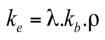
Where: λ, the proportionality constant λ = 0.346
kb , the thermal conductivity of the base material
ρ , the porosity (relative density) of as foamed RMF ~ 8%
Figure 1. 40 pores per inch (PPI) 6101 Al based metal foam consisting of nodes and ligaments forming a space filling network of dodecahedrons with 12 pentagon shaped facets.
The effective bulk conductivity of 8% dense 6061 Al RMF is about 4.7 W/m-K. Due to their high ductility, RMFs can undergo significant inelastic and elastic buckling deformations without failure of the ligaments, resulting in an increase in the relative density of the foam structure up to 50%. Since the thermal conductivity is a vector quantity, its value will be a function of not just the amount of compression (as it is for the effective surface area), but also of the direction of compression. The effective thermal conductivity of 6061 Al based foams biaxially increases to ~ 30 W/m-K when unidirectionally compressed in X direction to 50% relative density in the (YZ) plane where ligaments are aligned in Y and Z directions. As the cost depends on the volume as well, this feature allows optimizing both the thermal performance and the cost of RMF HX effectively and simultaneously [2].
Surface Area Density:
One of the most important features of the RMFs is their extremely high and scalable surface area density (ρs ) compare to those of brazed or extruded fins and fin pins. ρs is directly related to the extended surface area for improved convective heat transfer. The ρs of RMF was characterized using experimental measurements, by multipoint Brunauer, Emmett and Teller (BET) method by adsorption of krypton gas at 77.4 K, and the modelling studies by authors.
The results of these studies showed that ρs of 40 PPI RMF at as fabricated 6% and compressed 50% state are about 15.5 cm2 /cm3 (40 in2 /in3 ) and 138 cm2 /cm3 (350 in2 /in3 ), respectively [2,3].
Thermal Interfaces and Convective Film Coefficients:
An RMF based compact heat exchanger can be integrated to the sources of heat generation via solder bonding. Integration eliminates the highly resistive thermal interfaces of soft materials such as thermal pads, pastes or thermal epoxies commonly used to couple discrete devices, Hybrid Multi-Chip Modules (HMCM) of photonic and electronic devices to cold plates. An RMF may be brazed to low expansion skin layers and function as a constraining doublesided core heat exchanger (HX) for printed wiring boards (PWBs).
The RMF structure has a very high effective compliance, [2] that allows metallurgical bonding to the foam by soldering or brazing to low CTE materials (metalized ceramic plates, low expansion composites, Mo, and CuMoCu, among others). Since the CTE mismatch related thermal stresses and deformations are limited, the reliability of the integral heat exchanger, and the thermal base is not compromised, as verified by several hundreds of thermal cycles [5].
The mostly triangular cross section and only a couple of millimeter long ligament geometry of RMF offers significant advantages in convective cooling. It scales down the thickness of boundary layers, thereby generating vortexes and, inducing early transition to turbulent flow, and similarly delays or eliminates the transition from nucleate boiling to film boiling. The net outcome is enhanced heat transfer due to high local film coefficients.
Fabrication of RMF Heat Exchangers:
Method of manufacturing of RMS heat exchangers depends on the material and the design. Al RMF based HXs can be fabricated with vacuum or dip brazing. Fully enclosed HX/cold plate (CP) configurations require vacuum brazing using solid braze preforms. HXs with exposed RMF can be fabricated by either dip brazing or vacuum brazing. The open cell structure of RMF allows cleaning of any residual salts left over from the dip brazing bath. The advantage of vacuum brazing however becomes apparent for manufacturing in larger quantities. Use of a vacuum furnace may accommodate hundreds of units in a single batch operation at a lower cost per unit.
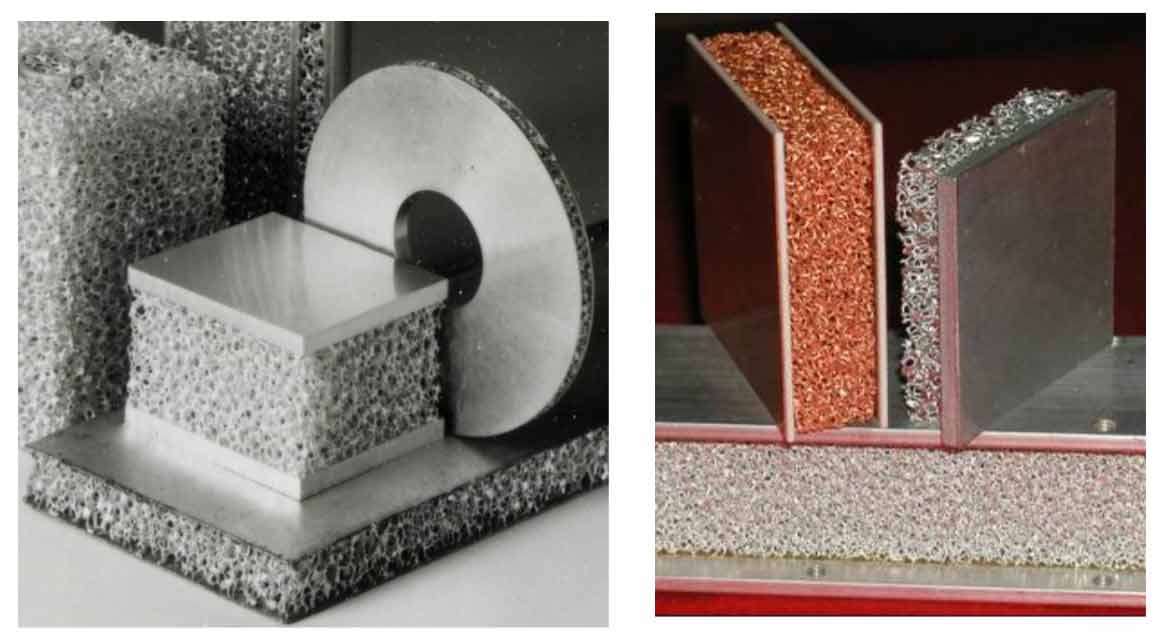
Figure 2. Precursors of Al and Cu RMF vacuum brazed HXs and CPs
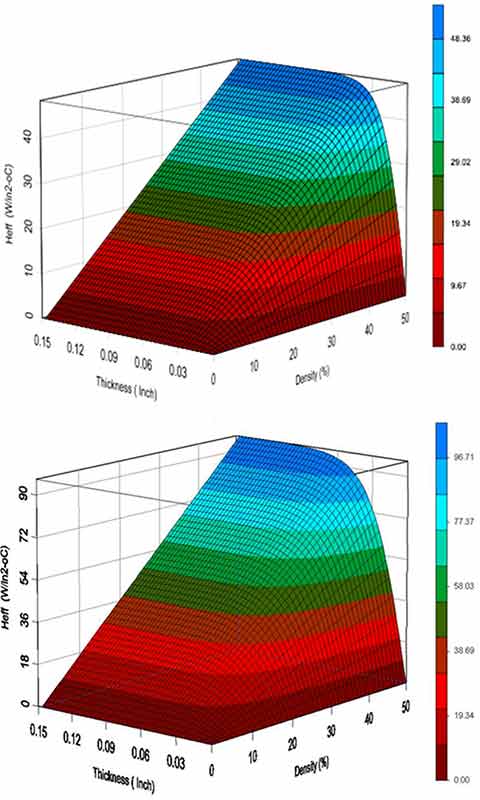
Figure 3. Effective h of 40 PPI 6061 Al (top) and Cu (bottom) RMF HXs with DI water at 63.1 cm3 /sec (1 GPM). The thickness range for both the Al and Cu foams is 0-38 mm. The ranges of effective heat transfer coefficient for the Al and Cu foams are 0 to 7.5 (W/cm2 o C) and 0 to 15 (W/cm2 o C), respectively.
The fabrication of Cu foam-based heat exchangers where Cu foam is bonded to a Cu plate of enclosed housing are fabricated with inert-atmosphere, high-temperature brazing or vacuum brazing furnaces with suitable Cu-Ag solid braze preforms. Solder pastes may be used to fabricate CPs in inert-atmosphere furnaces where RMF is exposed. Figure 2 shows aluminum foam-based articles made by vacuum brazing [6].
Thermal performance of RMF Heat Exchangers:
The major factors scaling the thermal performance of RMF HX are:
- Thermal conductivity of the base material (Al, Cu, Ag or others).
- Pore size measured as PPI, the linear density of pores per inch (5-40 ppi).
- Relative density (5% to ~50%)
- The thickness (similar to fin efficiency)
- Thermo-physical properties of the coolant
The recommended liquid coolants are distilled (DI)water, ethylene glycol, jet fuel, lubricating motor oils, Castrol, inert fluoro-carbons etc. Distilled water at 1 GPM flow rate was used as the coolant for generating the thermal performance surfaces shown in Figure 3 [2].
Experimental Study of Thermal Performance:
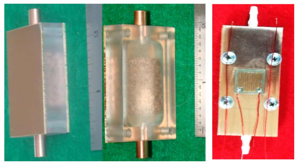
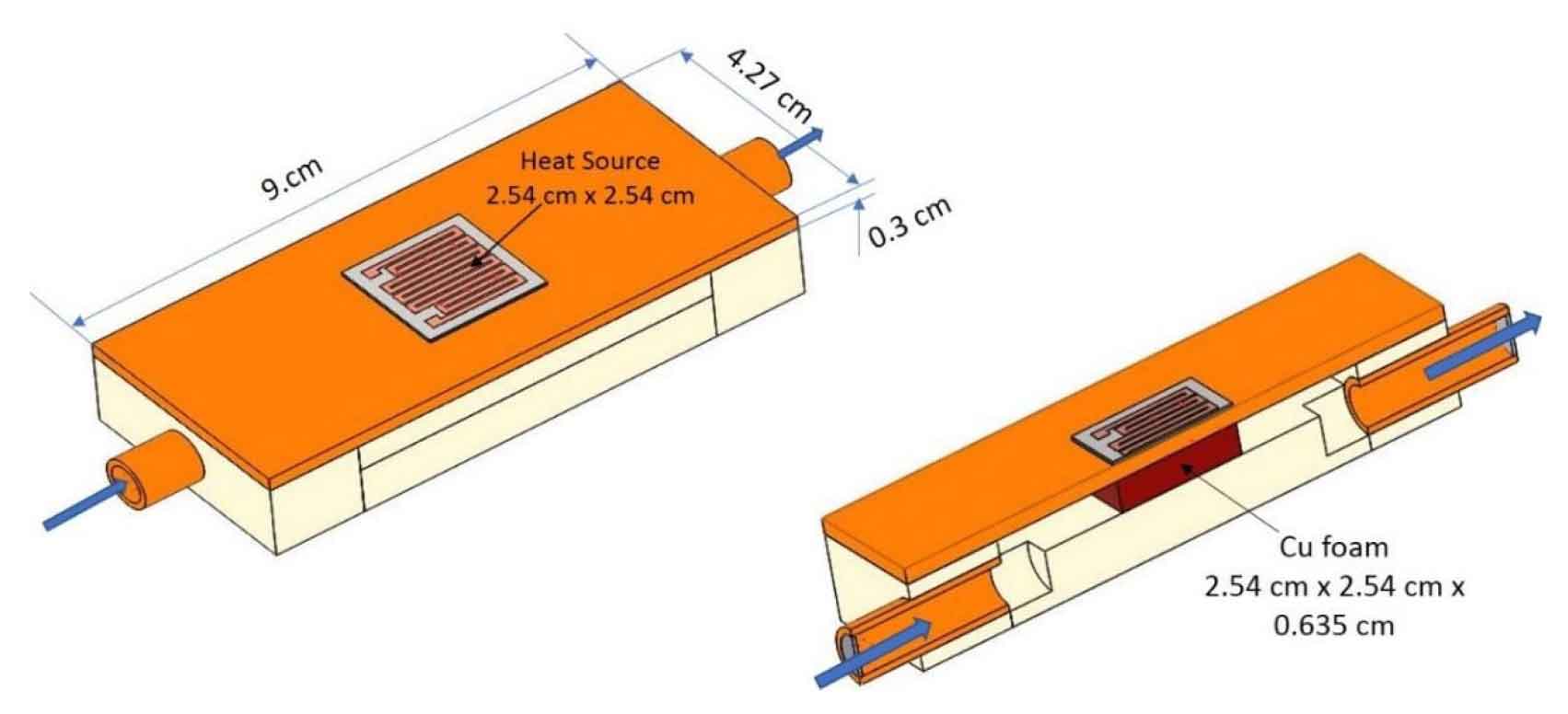
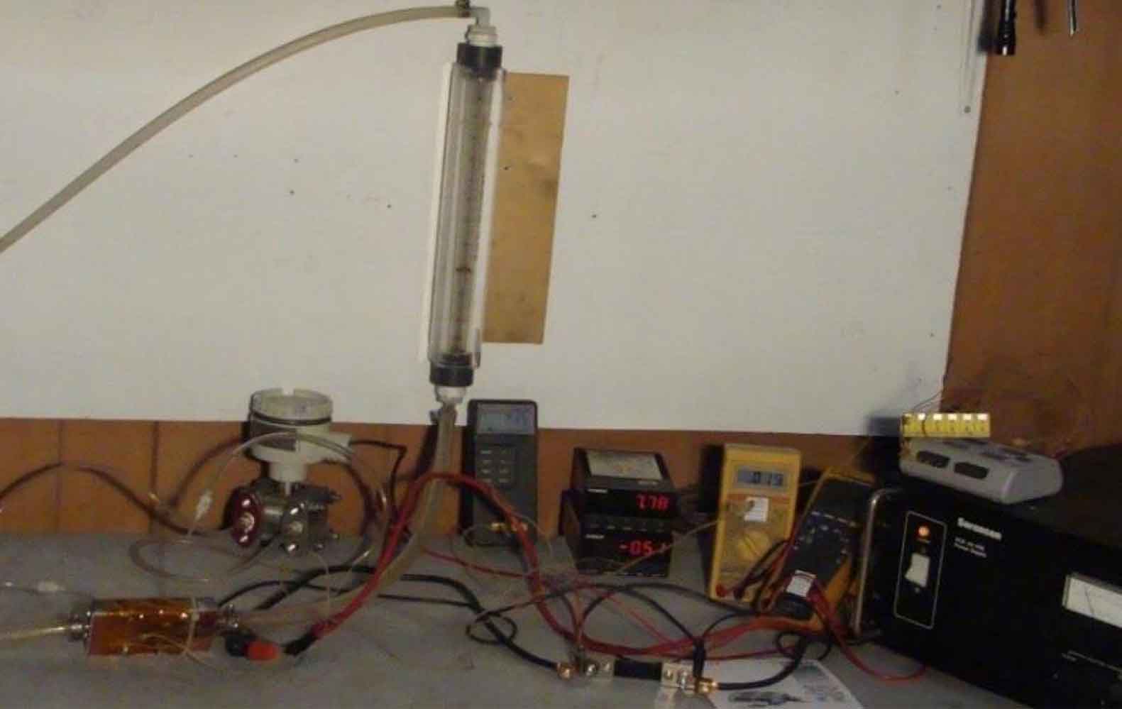
The test module was fabricated by inert atmosphere brazing a 2.54cm x 2.54cm x 0.635cm (1.00” x 1.00” x 0.250”) Cu block to the center of a 5.08cm x 5.08cm x 0.318cm (2.00” x 2.00” x 0.125” thick) Cu. A Plexiglas housing of the same cavity depth was fabricated out of a 0.635cm (0.250”) thick Plexiglass sheet and screwed to the Al and Cu plates with cork gasket. A 2.54cm x 2.54cm (1.00”x1.00”) resistor was eutectic Sn/Pb soldered on the center of the Cu Plate in inert gas environment. The flow rate and the inlet temperature of the inlet DI water were kept constant using a recirculating chiller. The volume flow rate, inlet and exit temperature of the coolant were monitored via flow meters and thermocouples. The surface temperature of the cold plate was estimated by the temperature measurements with thermocouples on the resistor. Pictures and drawing of the cold plate are depicted in Figures 4 and 5 respectively. The experimental setup and the test cold plate are shown in Figure 6.
Figure 4. Double and single sided see through functional cold plates (left), top view of the single sided test unit (right).
Figure 5. Figure 5. Drawing of the Cu RMF Cold Plate
Figure 6. Unit under flow and thermal resistance tests
Calculation of Effective Film Coefficient
The estimated local film coefficient of 1 W/cm20C for 63 cm3 /sec (1 GPM) flow rate was used in generating the thermal performance surfaces shown in Figure 3 [2].
The vertical axis is the effective flat plate film coefficient whereas the X and Y axis of the surface plot show the thickness and the density of RMF, respectively. The effective film coefficient is proportional to the density. The thickness of the RMF has a linear relationship with the effective film coefficient at low thickness which asymptotically approaches its saturation value with increased thickness, similar to that of the fin efficiency.
The average effective film coefficient may be estimated from the measured power input to the resistant heater, and the difference between the average temperatures of the coolant and the resistor as was done in authors laboratory. The results of such tests agree with the results of the calculations as presented in Figure 3.
Thermal Performance Comparisons:
The cold plate performance requirement for a high-power electronics device is defined by the thermal resistance. In the early stages of design, the feasibility of a given cold plate technology may be assessed by its thermal resistance (Rth) which is commonly calculated by Equation (2).
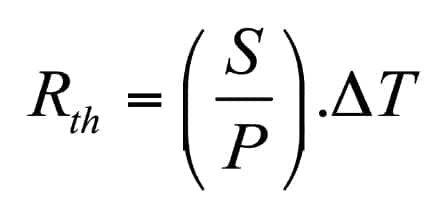
Where;
P: Power dissipated by the device
ΔT: Temperature difference between the maximum allowable surface temperature of the CP and the exit temperature of the coolant. ΔT may be calculated by Equation (3) where ρw=1000 (kg/m3 ), V= 6.3*10-5 m3 /sec (1.0 GPM), CPW=4184 (J/kg-o C), Tin=21o C, and the maximum allowed surface temperature of the cooled electronic device TMax=60o C.
(3)
Rth and Pressure Drop Measurements and Calculations:
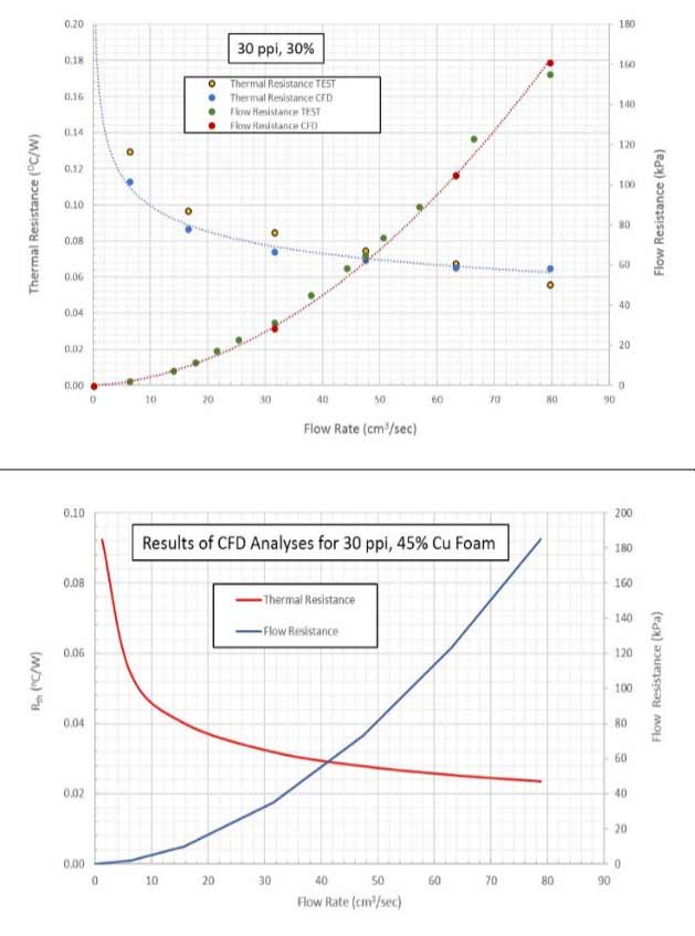
Rth was calculated using the above procedure. Specifically, the value of Rth at V= 6.3*10-5 m3 /sec (1.0 GPM) is equal to 0.042o C/W. The thermal resistance of the high performance micro channel type Cu cold plates, among others, is about 0.05o C/W under the same conditions. Graphs plotting values of Rth and pressure drop versus flow rate, based on measurements and CFD analyses, are presented in Figure 7.
Figure 7. Flow and the thermal resistances of Cu foam based Cold plates [6].
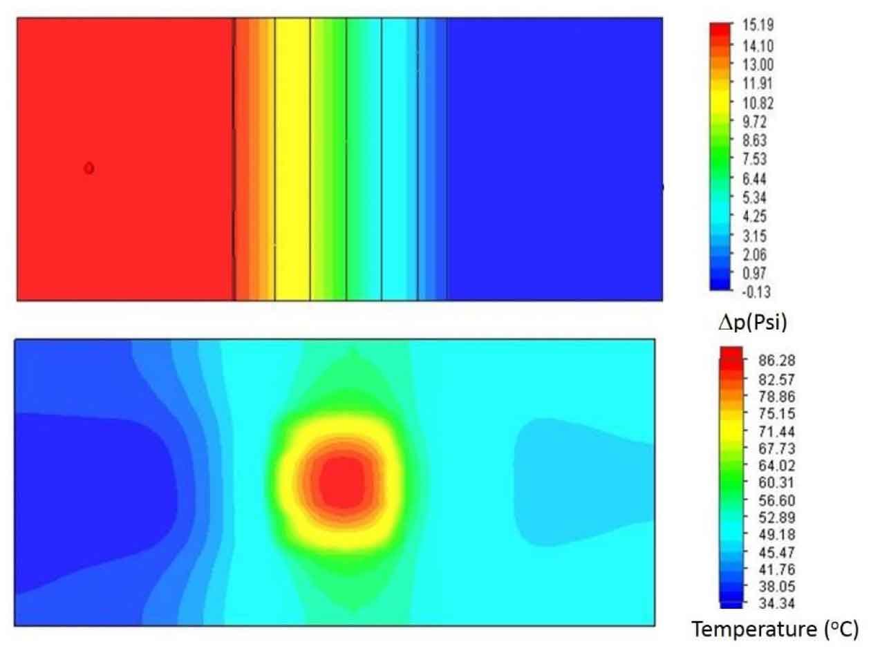
Figure 8. Distribution of differential pressure (top) and the surface temperature of the cold plate built with 30 ppi and 30% Cu RMF Foam at 1 GPM flow rate.
Effective film coefficients and surface area density of 30 ppi, 30% dense Al RMF were input to CFD using a proprietary method, to calculate the thermal and flow resistance of the test cold plate. The results of such calculations are shown in Figures 8 for 30 ppi 30% dense RMF Al cold plate and 30 ppi 45% dense RMF foam cold plates. Figure 8 depicts the results of CFD analyses for a cold plate built with 30 ppi, 30% dense Cu foam.
SUMMARY AND DISCUSSIONS
Studies show that RMF Based CP and HXs offer high thermal performance due to their extremely high specific surface area, local film coefficients and thermal conductivity particularly for lower volume and weight applications.
RFMs demonstrate compatibility with a wide range of liquids and gaseous coolants which makes the technology advantageously suitable for a wide range of commercial and military applications. The structural and thermal characteristics of RMF foams also offers similar advantages in passive phase change and two-phase flow applications.
REFERENCES
[1] Ashby, M. F. et al. “Metal Foams – A Design Guide”, Butterworth Heinemann, pp. 6-20, 2000.
[2] B. Ozmat et al., “Thermal Applications of Open Cell Metal Foams” Materials and Manufacturing Processes, Special Edition, Vol.19, No. 5, pp. 839-862, 2004
[3] Brunauer, Emmet, Teller, Journal of the American Chemical Society, Volume 60, 1938, p 309.
[4] Sorgo M., “Thermal Interface Materials,” Electronics Cooling, Vol. 2, No. 3, pp. 12 -16., Sept. 1996.
[5] Final Program Report, COMNAVSEASYSCOM contract N00024-94-NR58001.
[6] ergaerospace.com
