Joe Boswell, Chris Smoot, Elliot Short, Nate Francis
Introduction
In this study, lightweight two-phase heat sinks embedded with the Oscillating Heat Pipe (OHP) technology are developed for the thermal management of military circuit card assemblies (CCA). OHP-embedded heat sinks efficiently transport heat generated by CCA centrally located components to the assembly’s edges. Attention is paid to minimize the size, weight, cost and potential operability penalties associated with the incorporation of the OHP-embedded heat sink, to improve upon existing high performance heat sinks (e.g., Al-Be composites, encapsulated annealed pyrolitic graphite, or outfitted with Copper-Water heat pipes). This article provides a brief update on current OHP technology and summarizes initial findings from prototype OHP-embedded heat sinks.
Background
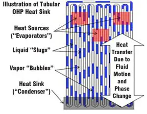
OHPs (or Pulsating Heat Pipes, PHPs), Figure 1, were invented by Akachi in 1990 [1] and first considered for adoption in electronics cooling applications in the early 2000’s [2]. They are passive two-phase cooling devices made from capillary-sized tubing that meanders in a closed- or open-loop channel pattern. This channel pattern is evacuated and partially charged with a working fluid and hermetically sealed. Heat is transferred by the working fluid’s latent and sensible heat as vapor bubbles expand, contract, and in turn oscillate the liquid slugs. No wick structures are involved. OHP-embedded heat sinks have proven capable of transporting kilowatt-level heat loads at effective thermal conductivities greater than 30kW/m-K [3]; and have proven reliable when operating in adverse gravity fields (e.g. up to 10g) [4]. Despite these attractive features, OHPs are not yet widely applied in electronics thermal management due to: perceived high costs, lack of predictability or information regarding reliability, and difficulty functioning at low temperature differentials (e.g., less than 15°C) [5].
Heat transfer mechanism
While OHPs are passive cooling devices, they operate like active, fluidly-pumped ones wherein the kinetic energy of the fluid comes from the thermal energy of the heat source(s) themselves. When at rest (i.e., uniform temperatures across the channel pattern), a well-designed OHP distributes its working fluid as a chain of liquid slugs and vapor bubbles throughout its channel pattern. OHPs start-up when a temperature differential is applied by heat sources (or heat sinks) and causes partial evaporation of nearby slugs (or condensation of bubbles). The fluid’s phase change results in volume and pressure differentials which in turn force the slugs and bubbles from relatively warm, high pressure areas (evaporators) toward cooler lower pressure ones (condensers) where a portion of the incoming bubbles condense, reject latent heat, and contract. The relatively cool fluid originally in the condensers is dislodged toward the evaporators through the channel pattern’s 180-degree turns. These movements disrupt (or oscillate) the working fluid chain, and new liquid slugs move into the evaporators, and the cycle repeats. Thus, OHPs utilize both the sensible (liquid flow) and latent (evaporation and condensation) heat of the working fluid. OHPs sustain this dual-mode heat transfer as long as the high-frequency phase change events continually disturb the system’s equilibrium; and working fluid temperature is sufficiently above its triple point (to maximize saturation pressure differentials and minimize liquid viscosity and density) yet below its critical point (to maximize surface tension and volume differentials of phase change events).
Manufacturability
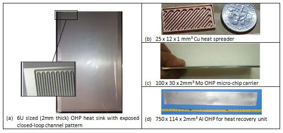
Ongoing research and development is being conducted not only on OHP design and modeling but also on reliable, affordable production methods to manufacture OHPs that are integral to the base material and delivered in either flat plate and/or three-dimensional form factors. OHPs have been successfully built with thicknesses varying from 0.75mm (0.030”) to 40mm (0.25”); lengths ranging from 25mm (1”) to greater than 750mm (30”); and manufactured from a variety of materials including Al, Cu, Ti, Mo, AlN, etc.; and paired with working fluids including water, acetone, common HCFCs, and nano-fluid derivatives of such fluids. Most lab-scale OHPs, Figure 2, are made from meandering tubing that is sealed and charged with working fluid.
Figure 1- Illustrated OHP with a chain of liquid slugs and vapor bubbles inside an 8-turn, closed-loop channel pattern.
Design and Predictability
An all-encompassing mathematical model of OHPs’ underlying thermo-physical events that enable their fluid oscillations and high heat transport capabilities has been an elusive goal of researchers since Akachi’s invention 25 years ago [7-13]. To manage the scope of this article, a brief introduction of key OHP design variables and a simplified method for estimating the affects of embedding an OHP inside a thermal module’s base material are presented herein.
Figure 2 -OHP based heat transfer technologies.
Two primary factors in designing an OHP are: 1) working fluid selection; and 2) channel pattern design. The working fluid is selected based on its thermophysical properties, compatibility with desired heat sink material, and the heat sink’s expected operating conditions (e.g., temperatures, heat loads, gravitational fields, etc.). Functional charging ratios vary from 10% to 90% of the OHP channel pattern’s empty volume [6]. The OHP’s channel pattern design considerations include: geometric constraints (e.g. external dimensions, through holes, etc.); turn-number [14]; relative location of heat source(s) and sink(s); manufacturing methods available for selected material; and (most notably) channel diameter such that the working fluid’s surface tension [15] and wetting of the material’s walls [16] maintain the chain of discrete liquid slugs and vapor bubbles.
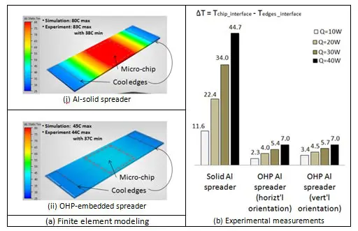
Once the OHP designer has completed selection of the working fluids, design of the internal channel pattern, and numerical modeling of the OHP’s evaporator-to-condenser thermal resistance (if such modeling is practical), a simplified Finite Element Modeling (FEM) approach can be used to estimate the OHP’s impact on the application’s overall thermal resistance. For steady-state modeling, the key thermal properties to customize are axial and radial thermal conductivities (kthermal) which can be deduced from the finite element model – or by referencing empirical results from similar OHP-embedded applications. Figure 3a is an example of how a simplified FEM approach can be used to reasonably predict an OHP’s affect on a module’s thermal performance. Figure 3(a,i) shows the predicted steady state temperatures of a solid Al heat spreader with three-dimensional kthermal of 167W/m-K; and figure 3(a.ii) an OHP-embedded Al heat spreader of equal dimensions and base material but embedded with a channel pattern with an axial-wise kthermal 5kW/m-K and a radial kthermal of 1W/m-K. Both units were simulated when attached to a 40W central heat source and two cold blocks at the units’ distant edges. Simulations predicted solid Al heat spreader maximum temperature of 80°C (or 44°C above its cold block interface); and the OHP-embedded unit’s maximum temperature of 45°C (or 7°C above its cold block interface). Prototype units were then fabricated and experimentally measured with a centrally located heat source and two cold blocks on each edge to match the operating conditions used in the simulations. The OHP unit was tested in both horizontal and vertical orientations to evaluate performance through a 1g field. Experimental results presented in Figure 3(b) closely match FEM predictions: at 40W of input heat, the solid Al unit’s measured maximum temperatures varied from 83-84°C (45°C above its cold block interface temperatures); and the OHP unit’s measured maximum temperatures were 44-45°C (7°C above its cold block interface temperatures) in both horizontal and vertical orientation. This modeling approach has proven predictive in other development efforts, including CCA heat sinks.
Figure 3 – Thermal comparison of Al-Solid vs OHP-embedded heat spreaders.
Fielded application
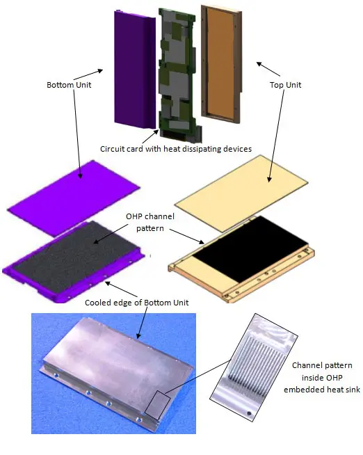
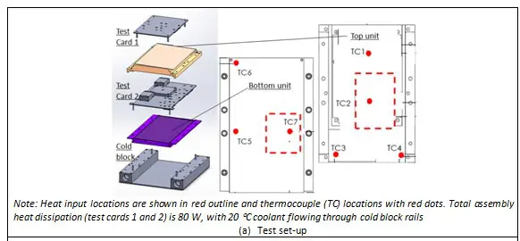
Based on the OHP’s inherent thermal features and recent manufacturing and design advancements, prototype OHP-embedded heat sinks have been produced for high power density military platform CCAs. In Figure 4 the top diagram illustrates the basic arrangement of the CCA and prototype heat sink which is comprised of a Bottom Unit and Top Unit that sandwich the CCA to acquire heat from the CCA’s devices and then conduct it to the Bottom Unit’s rails. Heat is rejected by the Bottom Unit’s rails which are in contact with the ultimate heat rejection medium (e.g. pumped liquid, forced air, etc.).
Prior to prototyping, FEMs prediction of a solid Al unit performance were compared to an OHP-embedded model. These initial models predicted that if the embedded channels assumed an axial-wise effective thermal conductivity of 1kW/m-K, then the maximum temperatures at the heat sink would drop by 2.5°C (compared to solid Al); and if the channels reached a 10kW/m-K effective thermal conductivity then the maximum temperatures would drop by 6.2°C. These levels of channel volume effective kthermal are within the bounds of previously achieved results of prior efforts of the authors (Figure 3) and other researchers [3, 5, 8, 17].
Figure 4- Illustration and photographs of CCA heat sink comprised of two components: a “Bottom Unit” (purple and on left) and “Top Unit” (beige and on right); The lower photographs are of a final OHP-embedded “Bottom Unit” with a zoomed-in view of its internal OHP channel pattern taken during fabrication.
With these targets in place, prototype Bottom Units and Top Units were fabricated, both from solid Al 6061 (kthermal = 167W/m-K) and from Al 6061 embedded with OHP channels as shown in Figure 4. The per unit price of the OHP-embedded units compared favorably to alternative high performance heat sink solutions.
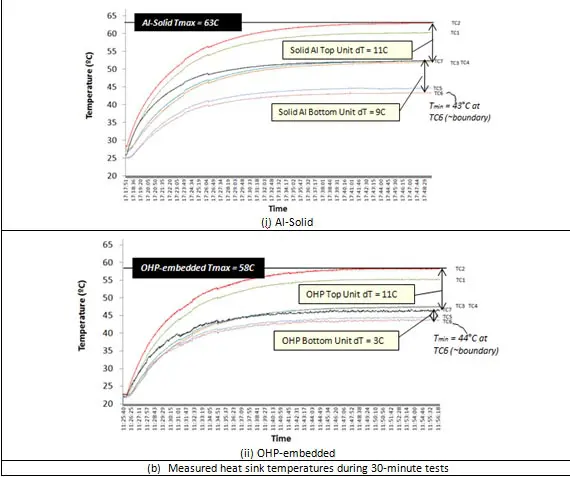
Initial test results for the thermal characterization of the OHP-embedded heat sink are presented in Figure 5(b.ii) with the corresponding performance of the Al-Solid sink given in figure 5(b.i). Figure 5(a) shows the locations of the heat sources (test cards 1 and 2) and of the thermocouples (TCs) measuring the surface temperatures of the heat sinks. In all tests, the total power dissipated by the test cards was 80W, and the heat dissipated through the heat sink into the cold blocks which were cooled by incoming 20°C coolant. The Al-Solid heat sink assembly was tested repeatedly to set a baseline (or control) for the OHP-embedded heat sink’s performance. Both the Al-Solid heat sink and OHP-embedded heat sink had similar boundary conditions (e.g. lowest measured surface temperatures on Bottom Unit near the cold block interface were 43° and 44°C, respectively).
Figure 5a
From Figure 5(b.ii), the OHP-embedded heat sink had a 5°C lower maximum temperature than the solid Al heat sink. The performance increase of the OHP was attributable to the 67% lower thermal resistance across the Bottom Unit’s surfaces. The temperature difference (dT) between Bottom Unit’s hottest location (TC7) to its coolest (TC6) reduced from 9°C in the solid Al unit to 3°C in the OHP embedded unit; and the working fluid’s oscillations are evident in the second-to-second temperature variations (i.e., the OHP’s TC7 varied by +/- 0.30°C over last 100 readouts whereas the solid control only varied by +/- 0.05°C over its last 100 readouts). On the other hand, the OHP in the “Top Unit” had minimal temperature improvement across its surfaces when compared to the solid Al unit. Both solid and OHP Top Units had temperature rises of 11°C across their surfaces (i.e., as measured from hottest location (TC2) to the coolest location (TC4) on the Top Unit). Oscillations are evident in the second-to-second temperature profiles of the OHP Top Unit (i.e., TC2 varied by +/- 0.2°C over its last 100 readouts), though such oscillations and temperature variations were less pronounced than in the OHP Bottom Unit. As of the date of this article, new OHP channel patterns are in development for the Top Unit to address its relatively large temperature rise to lower maximum temperatures across the heat sink by yet another 5°C.
Figure 5b- Measured thermal performance of Al-solid versus Al OHP heat sink.
Conclusion
The OHP technology is maturing as a real-world thermal management solution for engineers to consider as they seek to better control the temperatures across their electronics systems. Whereas OHPs from years past were unable to reliably operate with low temperature differences, today’s OHPs can provide outstanding effective thermal conductivity when operating with less than 3°C temperature difference between evaporator and condenser areas while still operating across a range of power levels and gravitational fields. OHPs are especially useful when the spatial distance between one or more heat sources and the heat sink(s) is at least 25mm – and OHPs have been proven effective at lengths as great as 750mm. Recent advancements in manufacturing and design, have enabled OHPs to be embedded inside a wide range of materials at production costs that are in-line or below (depending on the application) other high performance thermal management technologies. Ongoing research by the authors is investigating how to apply OHP-embedded solutions across range of military platforms and to further research the effects of long-term exposure to extreme thermal, vibration, shock and other environmental conditions.
Acknowledgements
This material is based upon work supported by a Phase II SBIR agreement with the Air Force Research Laboratory Space Vehicles Directorate Contract No. FA9453-13-C-0029. In addition, prior external research and development agreements helped make these materials possible, including: Phase I SBIR from National Science Foundation under Grant No. IIP-0912440; Phase I SBIR from Air Force Research Laboratory Space Vehicles Directorate under Contract No. FA9453-12-M-0026; Phase I SBIR from Office of Naval Research under Contract No N00014-13-P-1147; and Phase I SBIR from U.S. Navy NAVSEA under Contract No N00024-13-P-4562.
References
- Akachi, H. Structure of a Heat Pipe, US Patent No. 4921041, May 1990.
- Khandekar, S. An Introduction to Pulsating Heat Pipes. Electronics Cooling, 9(2), pp. 38-41, May 2003.
- Smoot, C. and Ma, H.B. Experimental Investigation of a Three-layer Oscillating Heat Pipe ASME Journal of Heat Transfer 136(5), February 2013, 051501, (6 pages).
- M. Thompson, A. A. Hathaway, C. D. Smoot, C. A. Wilson, H. B. Ma, R. M. Young, L. Greenberg, B. R. Osick, S. Van Campen, B. C. Morgan, D. Shararand N. Jankowski. Robust Thermal Performance of a Flat-Plate Oscillating Heat Pipe During High-Gravity Loading. ASME Journal of Heat Transfer 133(10), August 2011, 104504, (5 pages).
- Xu, J. L. and Zhang, X. M. Start-up and Steady Thermal Oscillation of a Pulsating Heat Pipe. Heat Mass Transfer, 41, March 2005, pp. 685-694.
- Khandekar, S. Thermo-hydrodynamics of closed loop pulsating heat pipes. Dissertation University of Stuttgart, July 2004.
- Khandekar, S., M. Schneider, and M. Groll. Mathematical modeling of pulsating heat pipes: state of the art and future challenges. Heat and Mass Transfer, SK Saha, SP Venkateshen, BVSSS Prasad, and SS Sadhal, eds., Tata McGraw-Hill Publishing Company, New Delhi, India, 2002, pp. 856-862.
- B.Ma, M.A.Hanlon, CL. Chen, An investigation of oscillating motions in a miniature pulsating heat pipe, Microfluidics and Nanofluidics, 2(2), 2005, pp. 171-179.
- Qu , H.B.Ma, Theoretical startup of a pulsating heat pipe, International Journal of Heat and Mass Transfer, 50 (11-12), 2007, pp. 2309-2316.
- Ma, H.B., Borgmeyer, B., Cheng, P., and Zhang, Y, Heat Transport Capability in an Oscillating Heat Pipe, ASME J. Heat Transfer, 130, 2008 pp. 0815011-7
- Shafii, Mohammad B., Amir Faghri, and Yuwen Zhang. Thermal modeling of unlooped and looped pulsating heat pipes. Journal of Heat Transfer 123(6), 2001, pp. 1159-1172.
- Zhang, Y. & Faghri, A., 2002. Heat transfer in a pulsating heat pipe with open end. Int. J. Heat Mass Transfer, 45, pp. 755–764.
- Cheng, P. and Ma, H.B.. A mathematical model of an oscillating heat pipe. Heat Transfer Engineering 32(11-12), 2011, pp. 1037-1046.
- Hathaway, A. A., C. A. Wilson, and H. B. Ma. Experimental investigation of uneven-turn water and acetone oscillating heat pipes. Journal of Thermophysics and Heat Transfer, 26(1), 2012, pp. 115-122.
- Taft, B., Williams, W., and Drolen, B.L., Review of Pulsating Heat Pipe Working Fluid Selection. Journal of Thermophysics and Heat Transfer 26(4) (2012), pp 651-656.
- Taft, Brenton, Sally Smith, and Jacob Moulton. Contact Angle Measurements for Advanced Thermal Management Technologies. Frontiers in Heat and Mass Transfer (FHMT), 5-1, 2014, (9 pages).
- Karimi, G., and J. R. Culham. Review and assessment of pulsating heat pipe mechanism for high heat flux electronic cooling. Thermal and Thermomechanical Phenomena in Electronic Systems, ITHERM’04. The Ninth Intersociety Conference on. Vol. 2. IEEE, 2004.

