Ercan M. Dede
INTRODUCTION
Single-phase liquid cooling is an established approach to the thermal management of highly-reliable hybrid vehicle power electronics. However, as the electrification of hybrid vehicles increases and under-hood space becomes further constrained, semiconductor device power densities continue to rise (in excess of 200 W/cm2) resulting in significant thermal management challenges. In response to this trend, there is sustained interest in the development of more compact, higher- performance cold plates for single-phase liquid cooling.
Fractal or branching microchannel flow networks have been identified to offer several advantages including low flow resistance [1], reduced channel wall temperatures [2], and greater overall cold plate temperature uniformity [3]. Generally, these performance benefits equate to lower system pumping power and better electronics temperature regulation. At the same time, a strategy to increase heat transfer in a more compact space is to stack multiple coolant channel layers for increased surface area and reduced unit thermal resistance [4, 5].
Building off of these two research directions, a single-device multi-pass branching microchannel heat sink was developed previously through the use of numerical gradient-based optimization techniques [6]. In this article, the design optimization of a related single-phase cold plate for the cooling of 12 large-area planar devices is briefly reviewed, and the fabrication and experimental testing of a prototype structure are described. The single-device cold plate geometry considered in [6, 7] is exploited as a periodic cooling cell in the development of a larger multi-device cooler, as described in [8], that also incorporates optimized global inlet and outlet manifold structures.
COLD PLATE DESIGN AND FABRICATION
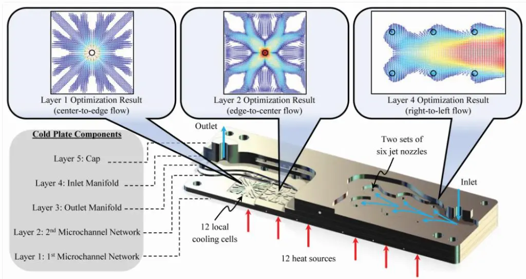
A sectioned perspective view of the multi-layer branching microchannel cold plate is shown in Fig. 1, where 12 local cells are placed in a periodic array for the cooling of multiple electronic devices; a cooling cell comprises microchannels arranged into two (Layer 1 and Layer 2) heat exchange passes. The optimal coolant flow paths used to develop the cold plate geometry are shown in the upper images of Fig. 1 using normalized fluid velocity vectors; note that larger velocities are shown in red. The branching channel flow maps, upper left and center images in Fig. 1, are obtained using a multiphysics topology optimization technique [6, 7], where the channel networks are found by minimizing an objective function comprising two terms related to the average temperature and fluid power dissipated in an assumed design domain. The optimization results serve as templates in the synthesis of the Layer 1 and Layer 2 microchannel designs. Alternatively, the Layer 3 (outlet) and Layer 4 (inlet) manifolds with wavy wall shape, upper right image in Fig. 1, are optimized for uniform fluid flow to the local cooling cells with minimum pressure drop [8, 9].
Figure 1 – Sectioned perspective view of multi-pass branching microchannel cold plate for cooling 12 electronic devices (lower image © [2014] IEEE. Reprinted, with permission, from [8]). Normalized fluid velocity vector flow maps (upper images) from structural optimization studies [6-9] with larger velocities indicated in red.
In the lower image in Fig. 1, the blue arrows indicate that the coolant enters through the vertical inlet of the cold plate at the right end. The coolant then travels horizontally through the inlet manifold and is evenly distributed in parallel via the first six jet nozzles to local microchannel cooling cells. From there, the coolant flows into the local Layer 1 (outward flowing) branching microchannel system. The coolant then reverses direction to flow radially inward through the Layer 2 branched microchannel network. Finally, the heated coolant empties into the Layer 3 outlet manifold, and the entire process repeats as two sets of six local cooling cells are connected in series to increase the flow rate to all cells.
The cold plate dimensions are 50 mm x 150 mm x 12.5 mm. Each jet nozzle diameter is 2.5 mm. The third and fourth layer manifold fluid passages are 2.54 mm in height. Layers 1 and 2 have microchannels that are 0.5 mm in height. Each local cooling cell covers a footprint area of 20 mm x 20 mm.
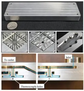
The cold plate is fabricated out of aluminum by precision machining the individual layers and diffusion bonding them to arrive at a unified structure [7]. The end result is a cold plate with minimal interfacial thermal resistance. Figure 2 illustrates the final assembled cold plate with zoomed views of the as-built microchannel/manifold geometry (middle row images) and cross-section (lower row images). The cross-section views show the inlet region of the cold plate (lower right) and a middle section of the cooler (lower left), where the blue arrows denote the coolant flow path and highlight the global flow transition from the first set of six cooling cells to the second set of six cells. Observe in Fig. 2 that a short microchannel height minimizes fin/channel distortion, and the diffusion bonding technique results in a continuous thermal path through the thickness of the assembly. Embedded thermocouple instrumentation holes are centered directly below each local cooling cell jet orifice.
EXPERIMENTAL FACILITY AND PROCEDURE
The experimental facility used for measuring the performance of the cold plate consists of a recirculating chiller, in-line filter, rotary-style flow meter, and test section. A standard 50/50 ethylene-glycol/water mix is used in all experiments. The test section comprises a 12-device heater assembly attached to the cold plate plus associated temperature and pressure drop measurement instrumentation. Flow test connectors are utilized to interface with the cold plate and provide for coolant inlet and outlet temperature measurements. A differential pressure transducer is attached to the cold plate via additional taps positioned just after the flow test connectors.
Figure 2 – Fully assembled cold plate (upper image). Zoomed views of Layer 1 and Layer 2 microchannels plus manifold geometry (middle images from left to right, respectively). Zoomed cross-section views of the inlet region with a single cooling cell (lower right image) and the middle transition region with a second cooling cell (lower left image). The blue arrows in the lower images indicate the coolant flow path. © [2014] IEEE. Reprinted, with permission, from [8].
Twelve aluminum nitride ceramic (250 W, 9.4 mm square) resistive devices are solder bonded to a specially designed
3.18 mm thick copper (Cu) plate for the heater assembly, which is bolted to the cold plate with a thermal interface material (TIM) grease layer in between. To determine power dissipation accurately, each device is wired in series to a shunt resistor for precise device voltage drop measurement. Each device/resistor arm is wired in parallel to a 1.4 kW power supply. Temperature measurements are acquired for each local cooling cell using calibrated thermocouples located as shown in Fig. 2. Heater assembly temperatures on the opposite side of the TIM interface are measured at the mid-plane of the Cu plate using thermocouples positioned in line with the cold plate thermocouples. Using a calibrated infrared (IR) camera, the device temperatures are additionally measured; note that the heater assembly is coated with high emissivity flat black paint for accurate thermal imaging.
Steady-state thermal-fluid performance of the cold plate is evaluated over multiple test runs at an elevated coolant inlet temperature. Coolant flow rates ranging from 0.5 to 2.5 L/min in 0.5 L/min increments are used. The supplied heater power is adjusted at each flow rate to achieve a maximum heater device temperature of ~125 °C (as verified via IR camera). Additional details regarding the test setup and experimental procedure are found in [8].
EXPERIMENTAL RESULTS
Figure 3 shows a representative thermal image of the heater assembly and devices taken at the maximum coolant flow rate of 2.5 L/min. The corresponding bar chart in Fig. 3 shows the experimentally measured cold plate, heater plate, and device average temperatures for each numbered cell in the IR image. The bar chart indicates that the cold plate temperatures are uniform to within 3.6 °C. A periodic trend in the heater temperatures is observed between the first row of device positions (i.e., 1-6) and the second row of positions (i.e., 7-12). Logically, heater temperatures closer to the bolts (i.e., positions 1, 6, 7, and 12) exhibit lower values due to reduced grease layer thermal resistance and possible heat sinking effects from the bolts. In Fig. 3, device 4 limits the total input power to the system with a maximum temperature of 127.4 °C. Positions 2, 4, and 5 have a larger temperature differential between each device average temperature and corresponding heater temperature indicating that the large-area solder bond layers for these devices likely contain well-known process-induced voids [10] leading to increased thermal resistance; see [8] for additional discussion.
After post-processing the experimental data by calculating the device power and performing a system energy balance, the cold plate convective thermal resistance is determined. Specifically, the device power is found by calculating the current using the known shunt resistance and corresponding measured voltage drop. A system energy balance is then performed to determine the power lost to the ambient environment (i.e., power in minus power out). The total input power to the system is the sum of the measured power to each device. The power carried out of the system by the coolant is determined using the known coolant specific heat capacity, measured coolant outlet-to-inlet temperature difference, and measured system mass flow rate. The thermal resistance of each cooling cell is then calculated by dividing the measured cold plate temperature minus coolant inlet temperature difference by the known device power (adjusted for power losses). The inlet temperature to the entire cold plate is used to calculate the thermal resistance of the first six cooling cells, while the inlet temperature to the second set of six cooling cells is specified as the cooler inlet temperature plus one-half of the rise in liquid temperature as measured from inlet to outlet. The reader is referred to [8] for additional details.
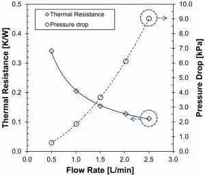
In Fig. 4, the cold plate thermal resistance (primary vertical axis) and experimentally measured pressure drop (secondary vertical axis) is shown as a function of flow rate with added trend lines. The pressure drop data in Fig. 4 is averaged over two test runs, while the thermal resistance data is further averaged across all 12 cooling cells. A maximum average cold plate thermal resistance of 0.341 K/W with a minimum average pressure drop of 0.59 kPa was determined at the lowest tested flow rate of 0.5 L/min. In contrast, a minimum average thermal resistance of 0.112 K/W with a maximum average pressure drop of 9.03 kPa was measured at the highest flow rate of 2.5 L/min. Explanation of experimental uncertainties and additional design performance verification by simulation is provided in [8].
Direct comparisons of cold plate performance are often challenging due to differences in the end application including the number of power devices, selected coolant, coolant flow conditions, cold plate material selection, and cooler size/packaging constraints. However, a recent investigation of advanced liquid cooling strategies for a representative traction drive application may be used for a rough comparison. Specifically, a definition of the coefficient of performance (COP) similar to [11] is assumed using only convective thermal resistance. Furthermore, the parallel operation of two branching microchannel cold plates is assumed for cooling approximately the same number of power devices. Based on these assumptions, the multi-pass branching microchannel cold plate is estimated to have a COP comparable to submerged jet-impingement on a micro finned enhanced copper surface, thus outperforming a traditional aluminum channel-flow cooling approach [11]. Here, a COP benefit for the branching microchannel cold plate is realized through a relatively low-pressure drop at a reduced flow rate.
CONCLUSIONS
This article provided the design and fabrication details of a unique compact multi-device branching microchannel cold plate developed for hybrid vehicle electronics. An experimental facility for measuring thermal-fluid performance was briefly described. Thermal resistance and pressure drop test results were outlined, and the presented cold plate design exhibits favorable performance.
Figure 3- Representative IR thermal image (on left) from the first experimental run at a coolant flow of 2.5 L/min. Bar chart (on right) of the cold plate, heater plate, and device average temperatures corresponding to the same test run. © [2014] IEEE. Reprinted, with permission, from [8].
While the multi-layer construction with the remote cooling strategy presented here necessitates diffusion bonding, more integrated layered designs may be achieved at the electronics substrate or semiconductor device level using well-established etching and deposition micro-fabrication techniques. Furthermore, the emergence of additive manufacturing technologies may further facilitate direct adoption of more complex three-dimensional cooling strategies in future electronics systems.
Figure 4 – Cold plate thermal resistance (average of 12 local cooling cells over two test runs) and pressure drop (average over two test runs) shown with trend lines as a function of flow rate.
From a design perspective, related optimization techniques may be applied broadly to address a variety of topics including, for example, liquid manifold design for two-phase cooling, heat sink design for air cooling, and composite microstructure design for heat flow control in electronics [9]. Thus, the use of optimization methods in the early stages of the product development process holds promise as an approach to the creation of highly efficient electronics thermal energy management solutions.
References:
[1] Bejan, A., “Constructal tree network for fluid flow between a finite-size volume and one source or sink.” Revue Ge´ne´rale de Thermique, 36(8), pp. 592–604, 1997.
[2] Pence, D., “The simplicity of fractal-like flow networks for effective heat and mass transport.” Experimental Thermal and Fluid Science, 34(4), pp. 474–486, 2010.
[3] Wang, X.-Q., Mujumdar, A.S., and Yap, C., “Thermal characteristics of tree-shaped microchannel nets for cooling of a rectangular heat sink.” International Journal of Thermal Sciences, 45(11), pp. 1103–1112, 2006.
[4] Vafai, K., and Zhu, L., “Analysis of two-layered micro-channel heat sink concept in electronic cooling.” International Journal of Heat Mass Transfer, 42(12), pp. 2287–2297, 1999.
[5] Wei, X., and Joshi, Y., “Stacked microchannel heat sinks for liquid cooling of microelectronic components.” Journal of Electronic Packaging, 126(1), pp. 60–66, 2004.
[6] Dede, E.M., “Optimization and design of a multipass branching microchannel heat sink for electronics cooling.” Journal of Electronic Packaging, 134(4), p. 041001 (10 pages), 2012.
[7] Dede, E.M., and Liu, Y., “Experimental and numerical investigation of a multi-pass branching microchannel heat sink.” Applied Thermal Engineering, 55(1–2), pp. 51–60, 2013.
[8] Dede, E.M., “Single-phase microchannel cold plate for hybrid vehicle electronics.” 30th Annual Semiconductor Thermal Measurement and Management Symposium (SEMI-THERM 30), pp. 118–124, March, 2014.
[9] Dede, E.M., Lee, J., and Nomura, T., Multiphysics Simulation: Electromechanical System Applications and Optimization, Springer, London, 2014.
[10] Ciappa, M., “Selected failure mechanisms of modern power modules.” Microelectronics Reliability, 42(4–5), pp. 653– 667, 2002.
[11] Waye, S.K., et al., “Advanced liquid cooling for a traction drive inverter using jet impingement and microfinned enhanced surfaces.” 2014 IEEE Intersociety Conference on Thermal and Thermomechanical Phenomena in Electronic Systems (ITherm), pp. 1064–1073, May, 2014.


