Ever hear about the 45° heat spreading angle? Most of us have. However, no one I’ve talked to seems to know where it came from. Is it an urban legend, such as alligators in the sewers of Manhattan, or is it an eternal truth deposited into the collective subconscious of the thermal engineering community? However fascinating it might be to explore the historical origins of this prescription, this column will content itself with merely examining its accuracy.
Figure 1a depicts a typical situation of the sort examined here. The component of interest is a block of material with uniform heat flux applied to the top surface. The bottom surface of the block is held at a constant temperature. There is no heat transfer from the sides of the block. Both the block base and the heat source are assumed to be square in shape.
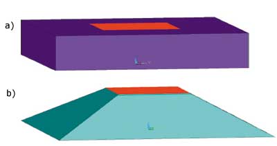 |
Figure 1a. Solid models. a) Square slab solid model with localized heated area.
Figure 1b. Pyramid solid model with 45° sides emanating from the heated area.If tasked with calculating the thermal resistance for heat to flow through block, one might begin to visualize flux lines emanating from the heat source and fanning out as the heat flows to the chilled base of the block. One could assume that the flux lines would be confined to a volume somewhere between the two extremes: pure 1-dimensional heat flow and pure lateral heat spreading. If one simply decided to split the difference between these limits, he would converge on the fabled 45° spreading angle. Figure 1b illustrates the resultant pyramidal envelope.
This column will explore two aspects of this problem:
1) How well does this 45° spreading angle approximation really work?|2) What is the best way to calculate a thermal resistance based on this approximation using simple formulas?
Accuracy of the 45° Angle Assumption
To answer this question, a series of simulations were performed using the Finite Element Analysis (FEA) method applied to the two geometries in Figures 1a and 1b. A commercial software tool was used [1]. The block width and thermal conductivity were assumed fixed at 10mm and 1 W/m�K respectively.
For completeness, a range of values of block thickness and heat source width were explored, 1 mm to 10 mm in each case. However, only a subset of these can be represented by the 45° pyramid. If the block is too tall for a given heat source size, the sloping surfaces of the pyramid will intersect the sides of the block. (The maximum block thickness for a given source width is WSOURCE + 2 x Thickness.) Table 1 provides the matrix of conditions used for the block analysis. The cross-hatched conditions were applied to the pyramid analysis.
Table 1. Matrix of Conditions Applied to Block Analysis. Cross-Hatched Conditions were Applied to 45° Heat Spreading Analysis.

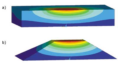 |
Figure 2. FEA thermal solutions of a) Slab and b) 45° pyramid. Models cut midplane to show temperature contours under heat source.For each of the conditions explored a thermal resistance was calculated in the usual way
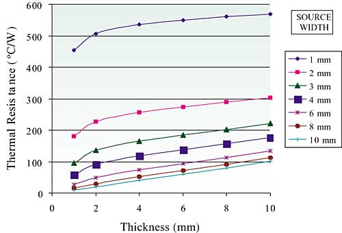
The graph in Figure 3a indicates the relationship between the thermal resistance and the thickness of the block for each of the heat source sizes analyzed. Here, the thermal resistance calculation is based on the peak source temperature. As is evident, the thermal resistance increases with increasing thickness. There is a purely linear relationship for the 10 mm source, due to the resulting 1-dimensional heat flow pattern. This relationship becomes increasingly non-linear with decreasing source width, suggesting the influence of an additional heat flow pattern.
Figure 3a. FEA thermal resistance results, slab, based on peak heat source temperature.
Figure 3b shows the calculated error for each of the conditions in the 45° pyramid analysis compared with the equivalent block solution. In all cases, the 45° pyramid demonstrated a higher thermal resistance than the block. The error increases with decreasing source size. The error is less than 10% for heat source sizes of 4 mm or greater. However, at the smallest heat source sizes evaluated, the error is as large as 30%. This behavior is indicative of the increased role of lateral heat flow from the source. For this size range, there is sufficient material beyond the heat source to provide a significant heat flow path to the base by way of the outer portions of the block, which is obviously not an option for the 45° heat spreading model. The reader should note that these results are general and not dependent of the assumed value of thermal conductivity.
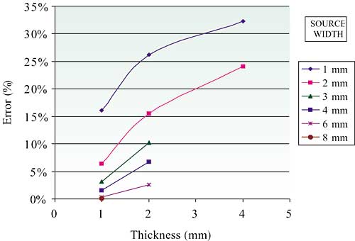 |
Figure 3b. Error calculated for 45° heat spreading model.
Analytical Calculation Methods
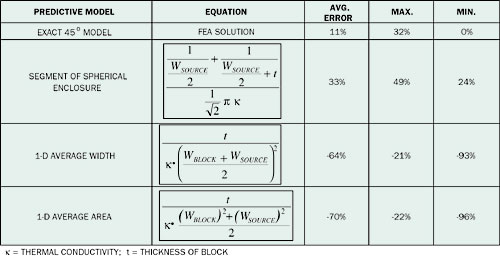
A number of candidate methods were evaluated. They are listed in Table 2. Of these the most accurate is that based upon the calculation for a segment of a spherical enclosure. This equation differs from its usual format [2] in that the spherical surfaces are assumed to subtend a solid angle of /(2)1/2 rather than 4
, representing approximately 18% of the total spherical surface. [Note: This spherical segment is essentially the intersection of a cone with a spherical shell. The sides of the cone form a 45° angle with its centerline, leading to a vertex angle equal to 90°.] This equation has the benefit of always providing an overestimate of the thermal resistance. The other two equations, modifications of the standard 1-dimensional formula provide underestimates of the thermal resistance and, as such, are less desirable. Error calculations based on the FEA results for average source temperature lead to increased error for the spherical enclosure and a decrease for the other two methods.Table 2. Error Analysis for Various Solution Methods Based on Peak Source Temperature in FEA Calculations.
 |
Conclusions
The 45° spreading approximation has been shown to provide reasonable accuracy in FEA calculations for components in which the size of the heat source area is greater than the component thickness. However, there would be little motivation to do so, since it is more difficult to construct the required pyramidal model than the more physically accurate slab model. The analytical methods evaluated here, however, provide limited accuracy. Of these, the spherical enclosure equation is recommended because it provides a conservative estimate of the resistance. For more precise calculations without resorting to the use of more elaborate simulation approaches, the reader is referred to the graphical method of Kennedy [3]. Undoubtedly, the 45° spreading approximation will continue to live in the folklore of thermal engineers for the foreseeable future. However, the prudent thermal engineer should be aware of its limitations in using it.
References
1. ANSYS®, Version 7.0. Suitable mesh refinement was performed to ensure accuracy for the smaller sized heat sources.
2. Carslaw, H.S., and Jaeger, J.C., Conduction of Heat in Solids, 2nd Ed., Oxford Press, London, 1959.
3. Kennedy, D.P., “Heat Conduction in a Homogeneous Solid Circular Cylinder of Isotropic Media,” IBM Technical Report 00.699, 1959. Summarized in: R. Tummala, E. Rymaszewski, and A. Klopfenstein, Eds., Microelectronics Packaging Handbook, 2nd Ed., Kluwer Academic Publishers, 1998.

