Introduction
This article will discuss air-cooled compact heat exchanger design using published data. Kays & London’s Compact Heat Exchangers [1] contains measured heat transfer and pressure drop data on a variety of circular and rectangular passages including circular tubes, tube banks, straight fins, louvered fins, strip or lanced offset fins, wavy fins and pin fins. While this book is the benchmark for air cooled heat exchanger test data, it makes no attempt to summarize the results or steer the thermal designer to an optimized design based on the different factors or combination of heat transfer, pressure drop, size, weight, or even cost. Using this reduced data and the analytical solutions provided, highly efficient compact heat exchangers can be designed. This article will guide a thermal engineer toward this optimized design without having to run trade studies on every possible heat exchanger design configuration. Typical applications of published fin data in the aerospace and military electronics include electronics cold plates, card rack walls, and air-to-air heat exchangers, both fan driven and ECS driven. Comparisons between fin performance are made and conclusions are drawn about the applicability of each type of fin to avionics thermal management.
 |
Using The Data
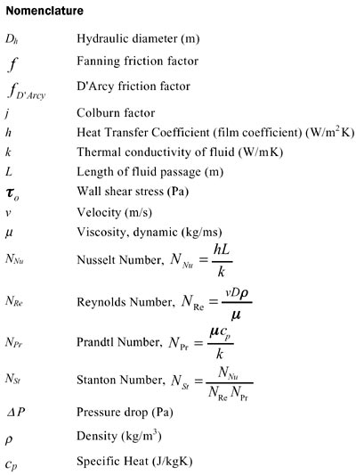
The data in Kays & London is presented as Fanning friction factor and Colburn factor vs Reynold’s number. The Fanning friction factor, also known as the skin friction coefficient, is defined as [2]
It is related to the more common D’Arcy friction factor by [2]
The pressure drop, using the Fanning friction factor provided by Kays & London, is given by [2]
 |
The Colburn factor, j is defined by [1]
 |
The film coefficient, using the Colburn factor provided by Kays & London is given by [1]
Finstock Geometry
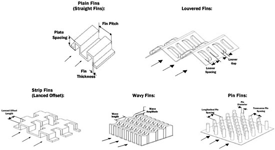
Kays & London provides data for many types of plate-fin surfaces including plain fins, louvered fins, strip (or lanced offset) fins, wavy fins and pin fins. With 56 plate-fin surfaces tested, there is a wide range of fin geometries for which data is directly available. Figure 1 shows five common plate fin types and the critical fin dimensions.
Figure 1. Fin descriptions.
Design Practices
Now that you have all this good information on heat transfer and pressure drop for the different extended surfaces, you need to find the best way to use it. In the past, the thermal engineer would open up the Kays & London textbook and look for a certain type of fin, such as pin, straight, lanced offset, or wavy, that worked for the combination of heat transfer, required pressure drop, and size constraints. This approach produces a design that works, but is hardly optimized for any of the considerations involved in designing the compact heat exchanger. A typical heat transfer plot of straight fins from Kays & London [1] is shown in Figure 2.
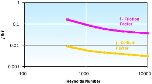 |
Figure 2. Finstock data # 14.77 from Kays & London (0.4 mm high, 0.15mm thick, 37.5 fins/mm, ST [0.330″ high, 0.006″ thick, 14.77 fpi, ST]).Figure 2 allows the thermal engineer to calculate the heat transfer and pressure drop by picking off the j-Colburn factor and friction factor at the proper Reynolds number for a certain configuration, but it is unknown whether the proper design was chosen from a size and efficiency standpoint. The first thing the thermal engineer needs to do is prioritize the design factors. Pressure drop, heat transfer, size, weight and cost must be placed in order of importance. Hence, figures of merit were developed in an effort to compare the different fin configurations.
If pressure drop and heat transfer are the most critical factors in the compact heat exchanger design then a good figure of merit is heat transfer per unit of pressure drop, or in basic terms: j-Colburn factor divided by f-friction factor. Figure 3 shows a comparison of the different types of extended surfaces using heat transfer/pressure drop as the figure of merit.
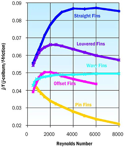 |
Figure 3. Heat transfer/pressure drop FOM.As can be seen from Figure 3, the efficiency of straight fins used in a heat exchanger is better than the other fin configurations over almost the whole range of typical Reynolds numbers. At a Reynolds number of 4000 the straight fin produces a three times better ratio of heat transfer per unit of pressure drop than the pin fin configuration. This figure of merit is based strictly on getting the best heat transfer for a given pressure drop.
Size is generally an important factor in the heat exchanger design. If size is the overall driving design factor then a good figure of merit is heat transfer per unit height. Figure 4 provides a comparison if size or height is the critical factor in the heat exchanger design. Figure 4 shows that, from a purely size standpoint, pin fins offer the smallest design for the best heat transfer while straight fins are the most inefficient from a heat transfer and smallest size constraint.
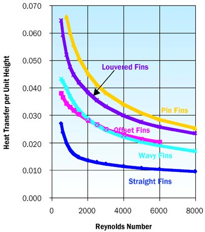 |
Figure 4. Size figure of merit.Weight is almost always an important factor in avionics cooling and designing a heat exchanger for an aircraft. A good figure of merit for weight is based on the heat transfer per weight unit. Figure 5 shows a comparison of fin configurations when weight is the critical factor in the design.
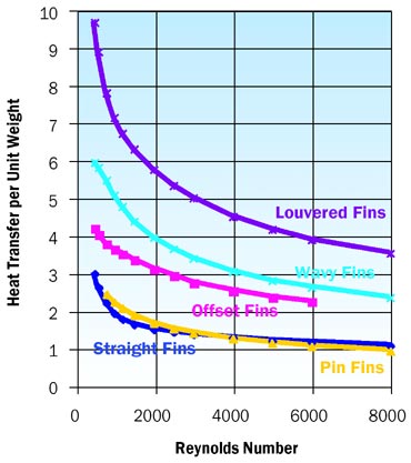 |
Figure 5. Weight figure of merit.The last parameter that must be traded is cost, which is always an important factor in the design of a compact heat exchanger. It is also one of the more subjective areas. In general, pin fins, which are incorporated directly into the casting of the heat exchanger, are the least expensive. The other fin configurations, such as wavy, straight, offset and louvered, cost about the same with some minor differences in set up costs.
A relative comparison of the fin configurations, based on all the factors discussed, is critical in determining the proper design. All of the parameters are presented as individual design points, while the charts show the relative comparison for one parameter such as size, the assumption is made that pressure drop is unlimited as well as weight or cost. All of these parameters must be considered to obtain the proper design. The table above summarizes or ranks each factor so that the thermal engineer can get a relative view of all the parameters together. The rankings in Table 1 are from 1 to 5 with a ranking 1 being the most desirable and a ranking of 5 being the least desirable.
Table 1. Comparison of All Parameters
|
With all of the parameters weighted equally the louvered fin configuration produces the best design for a compact heat exchanger. Another important factor is that even though the cost of the louvered fin is highest its cost is only slightly higher than the wavy, offset and straight fins. By contrast, the pin fin structure is an all or nothing configuration, with the highest figure of merits for cost and size, while performing extremely poorly in pressure drop and weight. So if cost and size are the number one priority without concern for pressure drop then the pin fins perform very well. Straight fins are also your best choice if pressure drop is the limiting factor in the design, which is usually a driving factor in avionics heat exchanger design. With all the parameters considered, all five fin configurations came out surprisingly equal, so a weighted average would be most appropriate in finding the proper design for a given set of prioritized factors.
Conclusions
A thermal engineer involved in air-cooled heat exchanger design should read and evaluate the wealth of data and knowledge provided in Kays & London’s book. Most people just read the empirical data represented at the back of the book for design purposes, but the entire textbook should be considered. Even though the first edition was written almost fifty years ago, almost all – if not all – of the information is still very applicable in this high tech age [5].
With avionics power densities increasing, it becomes even more critical to design an optimum compact heat exchanger to remove the heat load most efficiently. There are many factors to consider in the selection of fin style and geometry. All of the parameters discussed should help the thermal engineer understand and trade these factors so that the best design may be obtained. There will always be some give and take among all these factors, but knowing and evaluating these factors is critical in obtaining an optimum design.
References
- Kays, W. M. and London, A.L., Compact Heat Exchangers, 2nd ed., McGraw-Hill, New York, 1964.
- Incropera, F. P. and Dewitt, D. P, Fundamentals of Heat and Mass Transfer, John Willey & Sons, New York., 1981.
- Gerhart, P. M. and Gross, R. J., Fundamentals of Fluid Mechanics, Addison-Wesley Publishing Company, Massachusetts, 1985.
- Chapman, A. J., Heat Transfer, Macmillan Publishing Company, New York, 1974.
- Kays, W.M., London, A.L., Compact Heat Exchangers, 3rd ed., Krieger Publishing Company, Melbourne, FL 32902, 1984.

