By 2008 the electronics content of a typical consumer vehicle had grown to 20-25% of the total vehicle cost [1]. This content provides a wide range of functions and features for today’s driver. Some features such as the radio/audio system and instrument cluster are quite familiar and visible to the driver and have been mainstays in the automobile for many years. Other functions such as engine controllers and body computers (passenger comfort and convenience feature control) are less visible to the driver but are vital to the operation of the vehicle. The need for high reliability in the harsh automotive environment demands robust and capable cooling designs. These cooling systems need to be manufactured for the very high volume automotive market (> 60 million vehicles per year) at a low cost and with high quality. In addition to being environmentally friendly and recyclable, automotive electronic products also require maintenance-free operation during their greater than 10-year lifetime. The automotive electronics market is characterized by a wide range of vehicle types with varied functional content. Each of these vehicle types (motorcycles, light-duty cars or trucks, heavy duty on and off-road trucks, and construction or agricultural equipment) has a different range of environmental and operational requirements. There is also a wide range of electronic applications within each of these vehicle types including but not limited to: powertrain and emission controllers; vehicle body, antitheft, and comfort controllers; communication, navigation, display and entertainment systems; vehicle braking, traction/stability, steering, low tire warning, collision warning and airbag systems. Three product areas are currently seeing significant product proliferation: electric powertrain control for hybrid and electric vehicles, passenger and vehicle safety systems, and driver connectivity, including anti-distraction systems.
.”]
Power Dissipation Challenges and Design Approaches
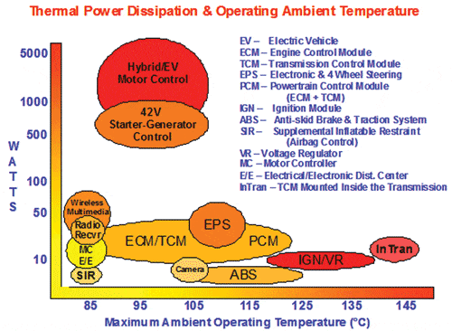
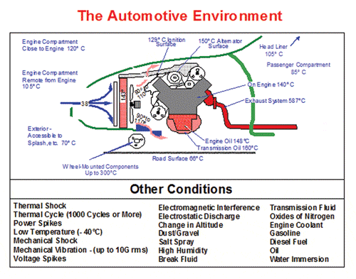
Most applications have waste power dissipation that ranges from milliwatts to 100 watts. However, waste heat for electric drive train controllers can be as high as several kilowatts. Also, electronic cooling designs are required to dissipate heat and be reliable in ambient temperatures ranging from -40°C to 150°C depending on the product mounting location within the vehicle. As a result, drivetrain applications require the use of high-performance cooling systems. The combination of high power dissipation and high ambient temperatures coupled with the previously discussed requirements for automotive applications create significant cooling design challenges. Figure 1 shows the power dissipation/ambient temperature requirements for representative automotive electronic product families. Products mounted outside the passenger compartment are also exposed to a wide range of fluids, vibration, and thermo-mechanical shock conditions. Figure 2 shows the full range of these vehicle environmental conditions.
Historically, most automotive electronics have been cooled convectively by ambient air. As indicated in Figures 1 and 2, maximum ambient air temperatures can vary significantly at various locations within the vehicle. As a result, even for products operating at comparable power levels, the design approach for electronics cooling will vary substantially in configuration and cost depending on the product mounting location within the vehicle. Whenever possible, the electronic product case, which in many instances is made of aluminum without cooling fins, is used as a thermal sink to ambient. If necessary, the case can be attached to a vehicle metallic structural member to conduct system heat to a larger surface area. Within the product enclosure, electronic devices are thermally attached to the case via thermally conducting grease or silicone pads, the choice being determined by the desired ambient-to-component junction temperature window. For power dissipations up to 30W, this approach can yield thermal resistance values for junction-to-case (θjc) in the 1°C/W to 2.5°C/W range, with case-to-ambient (θca) values of > 2°C/W.
As dissipation levels increase above 30 W, higher performance (higher cost) thermal interface materials and product case enhancements such as added cooling fins are required to reduce both θjc, θca into a range ≤ 1°C/W. In some instances, a bare chip die is attached to the product case with adhesives or thermal greases, which can also provide electrical isolation between the die and the case. Table 1 shows the thermal resistance values of some typical semiconductor packages used in automotive applications.
.”]
An Evolving Thermal Management Landscape
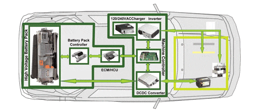
Over the past decade, the automotive electronics thermal management landscape has changed dramatically with the advent of hybrid vehicle electric drive trains (see Figure 3). The FET/IGBT semiconductor devices used in electrical power control systems, such as DC/AC inverters for electric motors and DC/DC converters for accessory power, can dissipate from several hundred watts up to tens of kilowatts of total power depending on the level of electric drive assist. Although conventional air cooling approaches can still be used for lower power mild hybrid vehicle assist systems, such as integrated starter/alternators, liquid cooling of the semiconductor devices becomes necessary for full hybrid systems. The most straightforward approach to cool these semiconductor devices is to use engine coolant, previously cooled by the vehicle radiator, flowing through cold-plates. In this situation, θjl (junction-to-liquid) thermal resistance values will be ≤ 0.5°C/W with maximum semiconductor junction temperatures of 150°C. However, this approach can add considerable cost, weight and volume to a hybrid vehicle drive system and there is a significant need for low-cost, high-performance cooling approaches.
For mild hybrid vehicles utilizing integrated starter/alternator systems, immersion cooling of power devices in a dielectric fluid has been used [3]. This is similar to the approach used for cooling the power system in locomotive engines in which the fluid provides convective and evaporative cooling. This method can reduce system volume and weight; however, ensuring fluid stability and containment integrity over vehicle lifetime presents additional technical and cost issues. Other possible approaches to liquid cooling include integrated liquid-cooled packages in which engine coolant is in contact with the electrically insulating power device substrate [4], or a secondary cooling loop using device packages where dielectric coolant flows directly over the power die [5]. These technologies can provide thermal resistance values of θjl < 0.2°C/W.
Many other components also require cooling. Bus capacitors and inductors can be effectively cooled by thermal conduction to the product case. The system battery pack can be cooled by forced-air convection through an appropriately designed package enclosure utilizing either ambient or passenger compartment air. In addition to air and liquid cooling technology, new developments in heat pipe/thermosiphon and thermoelectric cooling technology are being monitored.

Choosing Suitable Technologies and Materials for Cooling Structures
Just as crucial as the method of cooling are the materials used in cooling structures. Not only do they contribute to the thermal “stackup” resistance, packaging materials are also responsible for maintaining device integrity in a very demanding thermal environment. With power densities ranging from <1 W/cm2 to 400 W/cm2, the thermal management landscape in automotive electronics is very diverse. This requires a comprehensive approach for the selection of cooling technology, materials, and manufacturing processes.
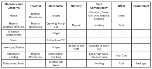
A wide spectrum of compatible materials (metals, semiconductors, ceramics, plastics, composites and possibly dielectric fluids) are required for robust automotive thermal cooling systems. Many unusual materials with specific properties are required to provide critical performance functions including thermal conduction, insulation, fluid transport, surface passivation, bonding and sealing, structural support or low friction interfaces. Careful selection of these materials on the basis of cost, performance, stability and mutual compatibility requires a detailed understanding of their thermal, mechanical and chemical characteristics.
The key high-reliability requirements for operating temperatures spanning -40°C to 150°C are thermal performance and stability. Composite and polymeric materials must neither be brittle nor exhibit excessive thermal softening. A careful selection of material thermal expansion coefficient differences must be made to control possible bulk mechanical fatigue, fracture or delamination of electrical interconnect structures and bonded surfaces. The material combinations selected must also accommodate thermal shock caused by power spikes which can reach 30°C/sec ramp rates on or near silicon devices.
Similar to thermal creep and expansion is the concern for mechanical wear-out of seals and diaphragms at their interfaces.
Thorough knowledge of material and function specifications coupled with experimental performance data can establish proper part geometries and the optimal material set for the required product life.
Thermal interface materials (TIMs) improve the thermal pathway at the interface of dissimilar materials by mitigating the effects of surface irregularities and air gaps. A variety of TIMs are available, such as semi-liquids, (thermal greases) and solid-state materials (pre-formed pads and curable TIMs) for this purpose. When using TIMs, potential areas of concern are mechanical pump-out of greases, dry-out of the continuous phase, and micro-structure fracturing.
When compared to radiation and conduction, liquid cooling offers improved thermal performance. The most common automotive cooling fluids are water-based. Water-based cooling fluids provide excellent thermal properties but also introduce significant design hurdles. Aqueous systems are notorious for promoting ionic corrosion. Additives and co-solvents address this concern and also provide freezing point depression and boiling point elevation while operating under pressures approaching 400 kPa (60 psi). However, high pressure and high flow rates in these fluid systems can cause mechanical wear of cooling system components.
In the future cooling systems may use heat transport fluids that come into direct contact with silicon power die. These high dielectric constant fluids (fluorocarbons) are not flammable and can be used in low pressure systems even under two-phase operation, but only provide a fraction of the heat transport capability of water-based systems. Chemical activity of these materials can be very low, but fluorine-based molecules pose significant compatibility issues with flexible tubing and many other halogen-based materials.
Therefore, it is important to use materials in the cooling system that have little to no interaction with these fluids.
Table 1.
Typical Semiconductor Thermal Resistance (°C/W) or Unit Thermal Resistance (°C cm2/W) Values Typical Semiconductor Thermal Resistance (°C/W) or Unit Thermal Resistance (°C cm2/W) ValuesTypical Semiconductor Thermal Resistance (°C/W) or Unit Thermal Resistance (°C cm2/W) Values
|
||||||||||||||

Conclusion
Most cooling system compatibility issues are those germane to the interior of the system. Externally, dust, debris and automotive fluids can foul heat exchanger surfaces and reduce heat transport efficiency.
Automotive electronic products are required to be reliable and maintenance-free in harsh operating environments for periods exceeding 10 years. However, these products also have to be produced in high volumes and at low cost. Some applications, such as hybrid vehicle drivetrain electronics, require liquid-cooling systems that can dissipate power levels exceeding 1 kW. The combination of these requirements is unique when compared to other consumer, commercial and aerospace electronic products. As a result, the design of the cooling systems required for automotive electronic applications demands careful technology development as well as long term material reliability and compatibility evaluations to ensure robust and reliable operation.
References
- “Electronics Penetration Has Leveled”, The Hansen Report on Automotive Electronics, Nov. 2006, Vol. 19, No.9, pg. 1.
- Myers, B.A., “Cooling Issues for Automotive Electronics,” ElectronicsCooling, Vol. 9, No. 3, August, 2003, pp. 30-34.
- Miller, J.M., “Propulsion Systems for Hybrid Vehicles,” Inst. Engineering Tech., 2004, p. 58.
- O’Keefe, M., Bennion, K., “Comparison of Hybrid Vehicle Power Electronics Cooling Options,” Paper NREL/CP-540-41886, January 2008.
- Sung, M.K., Muduwar, I., “CHF Determination for High-Heat Flux Phase Change Cooling System Incorporating Both Micro-Channel Flow and Jet Impingement”, Intl. Journal of Heat and Mass Transfer 52, (2009), pp. 610-619.
- Table 2. Summary of Cooling System Material Issues


