| Nomenclature
Variables |
|
| R | Thermal Resistance [°C/W] or [°C-mm2/W] |
| Q | Power [W] |
| Q” | Heat Flux [W/cm2] |
| T | Temperature [°C] or [K] |
| h | Heat Transfer Coefficient [W/cm2-K] |
| Subscripts | |
| sat | saturation |
| tc | thermocouple |
| s | sink or boiler |
| w | wall |
| j | junction layer of die |
| a | ambient |
| f | fluid or saturation |
| c | chip surface |
| boil | associated with boiling |
Introduction
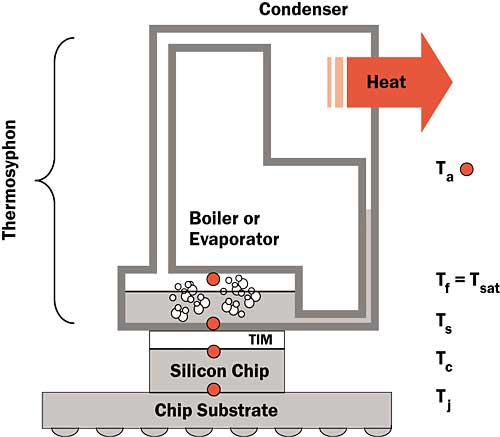
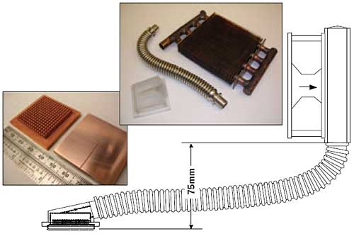
Thermosyphon technology has been used to cool electronic devices for many years. At its simplest, a thermosyphon is a hermetically sealed chamber partially filled with a volatile fluid and free of non-condensable gases. When heat is applied to the boiler (Figure 1), the fluid will evaporate or boil. The vapor will migrate to the condenser, which is cooled by external means, and condense. In this respect a thermosyphon is no different than a heat pipe. While both are passive devices, a thermosyphon differs from a heat pipe because condensate is returned to the boiler of a thermosyphon by gravity rather than by capillary forces. This limitation requires that the thermosyphon’s boiler be below its condenser.
Figure 1. Indirect Thermosyphon attached to a bare die processor.Thermosyphons do have some inherent advantages. First, there is no geometric constraint on the shape of the boiler. In some applications, this reduces the conduction resistances incurred when moving heat to the working fluid. Second, though there are less restrictive hydrodynamic limitations, there is no capillary limit impeding the return of condensate. Thermosyphons can, therefore, move heat large distances and dissipate it efficiently to large surfaces of any shape. Lastly, the connection from boiler to condenser can be quite flexible, allowing a thermosyphon of a given design to function in many geometric configurations. Thermosyphons have even been made of flexible polymeric films or bags.
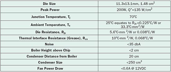
When compared with liquid phase pumped cooling technologies, a thermosyphon has the advantages of simplicity, small size and low cost. This article discusses an attempt to build an indirect, air-cooled thermosyphon that also performs as well as emerging forced water cooling technologies. The specific problem shown in Table 1 represents a high performance, dual core, bare die microprocessor. The relevant temperatures shown in Figure 1 are no different than those in a conventional heat sink application with the addition of a fluid saturation or boiling temperature, Tsat. The thermal resistance between the bottom surface of the boiler or sink temperature, Ts, and this saturation temperature is termed the boiling resistance, Rboil , or alternatively, Rsf.
Boiling Heat Transfer
The constraints shown in Table 1 allow only 0.119°C/W for Rsa. A good part of this will be condensation resistance. It is important to note that with an ambient temperature of 25°C and a realistic condensation resistance of 0.05°C/W, Tsat will be approximately 35°C for the 200W chip described in Table 1. Since Tsat dictates the saturation pressure and vapor density, it can have important ramifications for fluid performance. Though the condensation resistance is always significant, boiling resistance generally dominates and it has been the primary limitation in extant designs. Any discussion of thermosyphons, therefore, requires a basic understanding of boiling phenomena.
Table 1. Die Specifications and Targeted Thermosyphon Performance
The basics of saturated pool boiling can be found in most undergraduate texts. As the power or heat flux, Q”, to a surface immersed in a saturated liquid is increased from zero the surface temperature, Tw, will increase. At some point natural convection will give way to nucleate pool boiling. In this regime, the Wall Superheat (Tw-Tsat) is typically used to calculate the heat transfer coefficient, h. One can increase the heat flux in the nucleate boiling regime until it reaches the Critical Heat Flux (CHF) at which the vapor bubbles coalesce to form a stable film over the heated surface, effectively insulating it.
It is common to increase the CHF by means of extended surfaces, such as fins that project normal to the boiling surface. In such applications [1], the base area is commonly used to calculate the projected heat flux. Augmentation of the wetted surface with nucleation sites is a way to increase the local boiling heat transfer coefficient and CHF. Properly designed porous coatings [2], for example, produce embryonic bubbles that grow at low superheat. Porous metallic coatings [3] benefit from high thermal conductivity and can produce very high heat transfer coefficients. Such coatings can, of course, be applied to extended surfaces.
Though there are many fluids sufficiently volatile to be used in thermosyphons of the type described above, many have inherent limitations. Water, for example, performs well at higher pressures but suffers at the lower pressures dictated by a 35°C saturation temperature [4] and is prone to freezing. Hydrocarbon fluids are flammable. Materials halogenated with chlorine or bromine deplete the ozone layer. Perfluorocarbons (PFCs) have high global warming potentials and hydrofluorocarbons (HFCs) are being eliminated in many parts of the world for their contribution to global warming. Such HFCs are among the gases targeted in the Kyoto Protocol. Emerging regulatory policies are directed at reducing emissions of HFCs in a wide variety of applications through emission reporting, containment, reclamation, etc. [5]. Segregated hydrofluoroethers [6] (HFEs) remain a sustainable chemistry.
Boiler Design
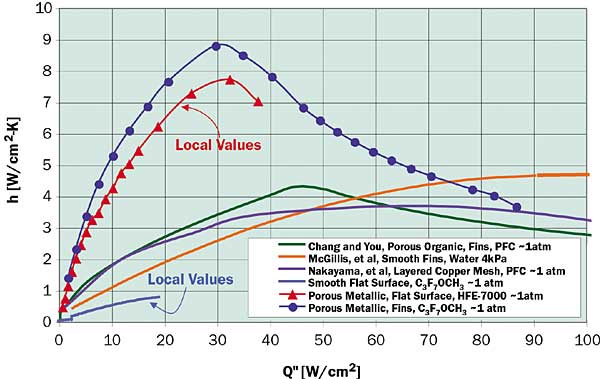
The boiling technology used in this work is a microporous metallic coating with pore size, porosity and thickness similar to the optimum values of Tehver [7]. Boiling the HFE C3F7OCH3 on a flat surface, the coating produces the local heat transfer coefficients shown in Figure 2. Also shown are the projected heat transfer coefficients achieved when this coating is applied to an array of square copper pin fins 1 x 1 mm and 4 mm long at a 2 mm pitch. Shown for reference are the data of Rainey et al. [8], boiling a PFC liquid from their organic coating applied to identical fins with 8 mm length. Also shown for reference are the data of Nakayama et al. [1], boiling PFC from their enhanced structure and the data of McGillis et al. [4], boiling water from optimized copper fins at 4 kPa (Tsat = 29°C).
Figure 2. Projected heat transfer coefficients as a function of projected heat flux for various pool boiling technologies.
A few things in Figure 2 are worthy of note. First, the peak projected heat transfer coefficient for the finned porous metallic surface occurs at a heat flux near 30 W/cm2. Peak projected heat transfer coefficients for the other technologies occur at significantly higher heat fluxes. Second, the finned porous metallic surface dries out at a projected heat flux of about 85 W/cm2, lower than the CHF of the other surfaces. These facts would appear to limit the utility of the finned porous metallic surface. However, the peak projected heat transfer coefficient for the finned porous metallic surface, at over 8 W/cm2-K, is significantly higher than those of the other technologies shown.
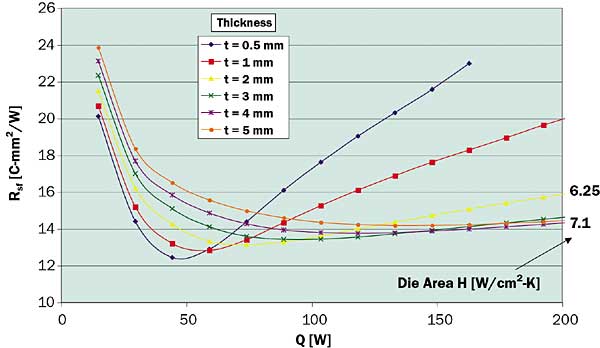
The CHF of the finned porous metallic surface precludes direct application to the 135 W/cm2 chip being considered here. Lateral spreading is needed to decrease the projected heat flux. However, because the projected heat transfer coefficient can vary dramatically across the wetted surface of such an extended boiler, conventional heat spreader correlations are not useful for design and numerical analysis is needed. The data shown in Figure 2 were used as boundary conditions in ANSYS simulations to determine the planar area and thickness of a finned copper boiler that would minimize Rsa when applied to an 11 x 13 mm source at 200 W (Figure 3). Interestingly, the effective (die area) heat transfer coefficient of a well-designed boiler in this case is not much lower than the peak projected value shown in Figure 2 and is still near 7 W/cm2-K as the power approaches 200 W.
Figure 3. Modeled sink-to-fluid thermal resistances for an 11 x 13 mm heat source applied to a pin fin boiler with a porous metallic coating of the present work. Boiler is 22 x 26 mm by thickness shown in the legend.
Fabrication and Test
The boiler fabricated for this project is shown in Figure 4. It was roughly 40 x 40 mm, 4 mm thick and made of high purity copper. A thermocouple in the bottom (chip side) of the base terminating at the centerline permitted measurement of Ts. Tsat was measured inside an injection molded epoxy cap (Figure 4) that produced a cavity 27 X 27 mm and 10 mm above the base of the boiler. A 20 cm long, 3/8″ I.D. corrugated tube coupled the boiler assembly to one of two finned-tube condensers. One was 100 x 100 mm and the other 100 x 200 mm.
Figure 4. Boiler, cap, tube, 100 x 100 mm condenser and the assembled test configuration.
The system was charged with 20 cc of C3F7OCH3 (boiling point 34°C) and degassed. A silver-based grease and clamps coupled the boiler assembly to an 11.3 x 13.1 mm copper die simulator. The temperature, Ttc, measured with a thermocouple 1mm from this surface was corrected at each heat flux using Fourier’s law to attain the actual chip surface temperature, Tc.
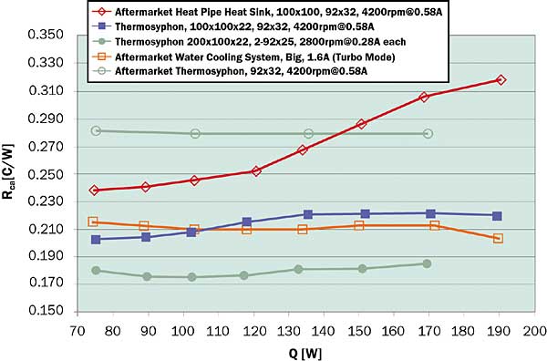
Figure 5. Results for thermosyphon testing on 11.3 x 13.1 mm copper test die. Legend shows the condenser size followed by the fan configuration.
Test Results
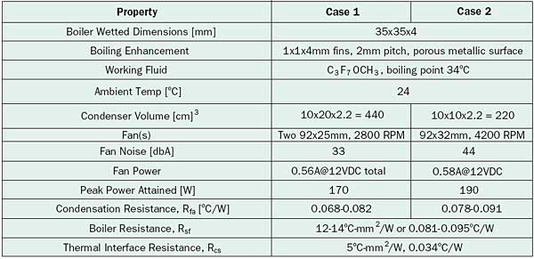
Figure 5 shows Rca values for the thermosyphon described above for different condenser and fan configurations. The legend shows first the condenser size followed by the fan size, speed and rated current draw. Also shown for reference are data gathered with commercially available aftermarket cooling solutions tested on the same chip simulator. The first is a high performance copper heat sink constructed with four heat pipes. The second is a thermosyphon with integrally mounted evaporator and condenser. Both of these were tested with the same 92 mm fan used for Case 2 in Table 2. The last is a forced convection glycol/water system. This was tested with the stock 120 x 38 mm fan and the total current draw (pump and fan) was measured.
Table 2. Actual Thermosyphon Specifications and Performance
The thermosyphon compares favorably with the aftermarket technologies. Although entrainment of falling condensate by rising vapor in the 9.5 mm (3/8″) ID tube prevented the thermosyphon from reaching 200 W, this is easily avoided by using a larger tube or smaller and separate vapor and condensate tubes. Using the die resistance shown in Table 1, one can project that the 70°C target junction temperature is easily reached with the 100 x 200 mm condenser using two 92 x 25 mm fans drawing less than 0.6A. The ability to reach the target junction temperature has to be attributed in part to the 5°C-mm2/W interface resistance achieved. Experimental sink-to-fluid resistances near 200 W are 12-14°C-mm2/W, very similar to those of Colgan et al. [9]. Using the 60°C approach temperature difference allowance of Ellsworth and Simons [10], a heat flux of 250 W/cm2 would be allowed for the die considered.
Conclusions
A thermosyphon was built that is capable of removing 200 W from an 11 x 13 mm die with a 70oC junction temperature. It uses only 20 cc of C3F7OCH3 to achieve Rsf values of 12-14oC-mm2/W. This is competitive with emerging forced convection water technologies.
It should be noted that the boiler resistivity (C-mm2/W) cannot be considered a constant for this technology. It will be dependent not only on heat flux but may, when lateral spreading is used, depend upon heat source size as well.
Much boiling research has focused on maximizing the projected CHF. However, the lowest Rsf achievable with a given boiling technology is not necessarily achieved by boiling at its maximum attainable projected heat flux. The optimum performance may be achieved with a boiler design that incurs a lateral spreading resistance.
Acknowledgement
The authors would like to thank Larry Stang and Gary Palmgren for their significant contributions to this work.
References
- Nakayama, W., et al, “Heat Sink Studs Having Enhanced Boiling Surfaces for Cooling Microelectronic Components,” ASME Paper No. 84-WA/HT-89, 1984.
- Chang, J.Y. and You, S.M., “Boiling Heat Transfer Phenomena from Microporous and Porous Surfaces in Saturated FC-72,” IJHMT, Vol. 40(18), 199, pp.4437-4447.
- Webb. R.L. “Principles of Enhanced Heat Transfer,” John Wiley and Sons, New York, 1994. (Note: This contains a good discussion of porous metallic coatings and boiling enhancement in general.)
- McGillis, W.R., et al, “Pool Boiling Enhancement Techniques for Water at Low Pressure,” WRL Research Report 90/9, Western Digital, Dec. 1990.
- Council of the European Union Document 16056/5/04 REV 5.
- Tuma, P.E., “Segregated Hydrofluoroethers: Long Term Alternative Heat Transfer Liquids,” Proceedings of the 2000 Earth Technologies Forum, Oct. 30-Nov. 1, Washington, D.C., pp. 266-275.
- Tehver, J., et al, “Heat Transfer and Hysteresis Phenomena in Boiling on Porous Plasma-Sprayed Surface,” Experimental Thermal and Fluid Science, Vol. 5, 1992, pp. 714-727.
- Rainey, S.M., You, K.N., and Lee, S., “Effect of Pressure, Subcooling, and Dissolved Gas on Pool Boiling Heat Transfer from Microporous, Square Pin-finned Surfaces in FC-72,” IJHMT, 46, 2003, pp. 23-35.
- Colgan, E.G., et al, “A Practical Implementation of Silicon Microchannel Coolers for High Power Chips,” 21st IEEE SEMI-THERM Symposium, San Francisco, California, Mar. 2005.
- Ellsworth, M.J. and Simons, R.E., “High Powered Chip Cooling,” ElectronicsCooling, Vol. 11, No. 3, Aug. 2005, pp. 14-22.

