Introduction
With thermal solutions becoming more challenging, there is a push for novel cooling ideas or materials to further mitigate thermal issues facing today’s electronics. In these design situations, the proven method of analytical calculations, modeling, and laboratory testing is sometimes bypassed in the search for a quick “cure-all” solution. Evolutionary progress is needed in the thermal industry of course. However, in a rush to implement new ideas/materials thorough testing should not be overlooked in determining thermal performance of a solution before implementation.
 |
Table 1. Heatsink Geometry
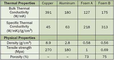
The stated thermal properties of engineered graphite foams have been a motivator for their consideration as heat sink materials. Yet, the literature is void of true comparison of these materials against copper and aluminum. To address the issue of graphite foam as a viable material for heat sinks, a series of tests were conducted to compare thermal performance of geometrically identical heat sinks (Table 1) made of copper, aluminum, and graphite foam (Table 2). These tests were conducted in a research quality laboratory wind tunnel where the flow was unducted consistent with most typical applications. The results for the ducted and jet impingement flows, though similar to the unducted case, will be presented in a future article along with a secondary graphite foam material, “foam B”.
 |
Table 2. Comparative Thermal and Physical Properties of Metals and Foams
Test Procedure
Prior foam experimentation by Coursey and Boudreaux [1] utilized solder brazing to affix the foam heatsink to a heated component. This solder method was chosen to reduce the problematic interfacial resistance when using foams due to their porous nature. Directly bonding the heatsink to a component has two potential drawbacks. The first involves the high temperatures common in brazing, which could damage the electrical component itself. The other drawback of soldering involves the complication of replacement or rework of the component. Due to the low tensile strength of foam, (Table 2 [2]), a greater potential for heatsink damage occurs when compared to an aluminum or copper variant. If the heatsink is damaged, or if the attached component needs to be serviced, the bonding method increases the cost of rework.
To avoid these problems it is possible to solder the foam heatsink to an aluminum or copper carrier plate. This foam and plate assembly could then be mounted to a component in a standard fashion. This carrier plate would also allow for sufficient pressure be applied to the interface material, ensuring low contact resistance.
In this study the heatsinks were clamped directly to the test component without a carrier plate for a standard across all three materials. A high performance thermal grease [3] was used as an interface material to fill the porous surface of the foam and reduce interfacial resistance compared to a bare joint.
A total of five J-type thermocouples were used during the testing, they were placed upstream of the heatsink to record ambient air temperatures, in the heater block, in the center of the heatsink base, at the edge of the heatsink base, and in the tip of the outermost fin.
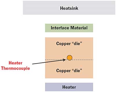
A thin film heater was set at 10 watts during all testing, and the heat source area was 25 x 25 mm, or a quarter of the overall sink base area, Figure 1. To insulate the bottom of the heater both cardboard and FR-4 board were used, the estimated value of Ψjb is 62.5°C/W. Throughout testing the value of Ψjb was 36 – 92 times greater than that of Ψja.
 |
Figure 1. Exploded view of the heatsink test assembly.
Results
As expected, the traditional copper and aluminum heatsinks preformed similarly, the main difference being due to the higher thermal conductivity of copper, which reduced spreading resistance.
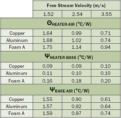
During low velocity flow conditions the lower heat transfer rate dictates that the convection thermal resistance makes up a large portion of the overall Θja. As flow speed increases, the convection resistance decreases, and the internal heatsink conduction resistance becomes more of a factor in the overall Θja value. This behavior is evident when comparing the different heatsink materials. The graphite heatsink thermal performance was only 12% lower than aluminum at low flow rates, while this performance difference increased to 25-30% as the flow rate increased (Table 3) .
 |
Table 3. Specific Thermal Test Results
Due to the lack of a solder joint, the foam heatsink experienced a larger interfacial resistance when compared to the solid heatsinks. This difference can be seen when comparing ΨHEATER-BASE in Table 3. To decouple the effect of interfacial resistance ΨBASE-AIR can be calculated. When ignoring interfacial resistance in this manner foam performs within 1% of aluminum at 1.5 m/sec (300 lfm), and within 15% at 3.5 m/sec (700 lfm).
Conclusion
Graphite foam derived heatsinks show promise in specific applications, but exhibit several drawbacks in the mainstream electronics cooling industry. Due to the fragile nature of graphite foam, unique precautions must be taken during the handling of the heatsink and its use. When coupled to a copper base plate, graphite foam can perform with acceptably small spreading resistances. However the lower thermal conductivity of the foam reduces thermal performance at high flow velocities when compared to a traditional copper heatsink.
The mechanical attachment needed to ensure acceptable thermal interface performance without soldering or brazing is also an issue that prevents a foam based heatsink from being explored in many mainstream applications. Despite these challenges the thermal performance to weight ratio of foam is very attractive and well suited to the aerospace and military industries were cost and ease of use come second to weight and performance.
References
- Coursey, J., Jungho, K., Boudreaux, P. “Performance of Graphite Foam Evaporator for use in Thermal Management,” Journal of Electronics Packaging, Vol.127, June 2005, pp. 127-134.
- Klett, J., “High Conductivity Graphitic Foams,” Oak Ridge National Laboratory, July 18, 2003, pp.1-53.
- Shin Etsu X23.


